I’ve been playing with Arduino (technically, ESP-M3) and a cheap 433 MHz receiver I picked up from eBay, model MX-RM-5V (also marked 080408). I managed to get a basic program working that used RCSwitch and PubSubClient to push message information to my MQTT server when I pressed a button on an inexpensive Spigen 433MHz doorbell I had purchased, but unfortunately the range was limited to only about a yard. I understood that adding an antenna to these receivers had the potential to significantly increase the range, but everything I found suggested that the receiver I was working with was slightly different than the standard MX-RM-5V receiver, and that my antenna attachment pad actually sat between the two contacts for the induction coil. I tested the attachment of an antenna here, and found that it didn’t work. Every picture I could find of this receiver showed a different induction coil than what I had.
Today, it finally occurred to me that maybe my receivers had been made incorrectly. Since I’d ordered a four pack, I dug through the other three, and sure enough, two of them have the three coil inductive loop seen on every picture of these on the Internet, and connected to the pads they are typically connected to. The other two – including the one I happened to chose to work with – have an eight coil inductive loop, which bears a suspicious resemblance to the inductive coil present on the transmitter. Looks like I just happened to be the lucky guy who received the components assembled by the new guy on the production line. Wanted to share this in case a similar issue comes up for anybody else.
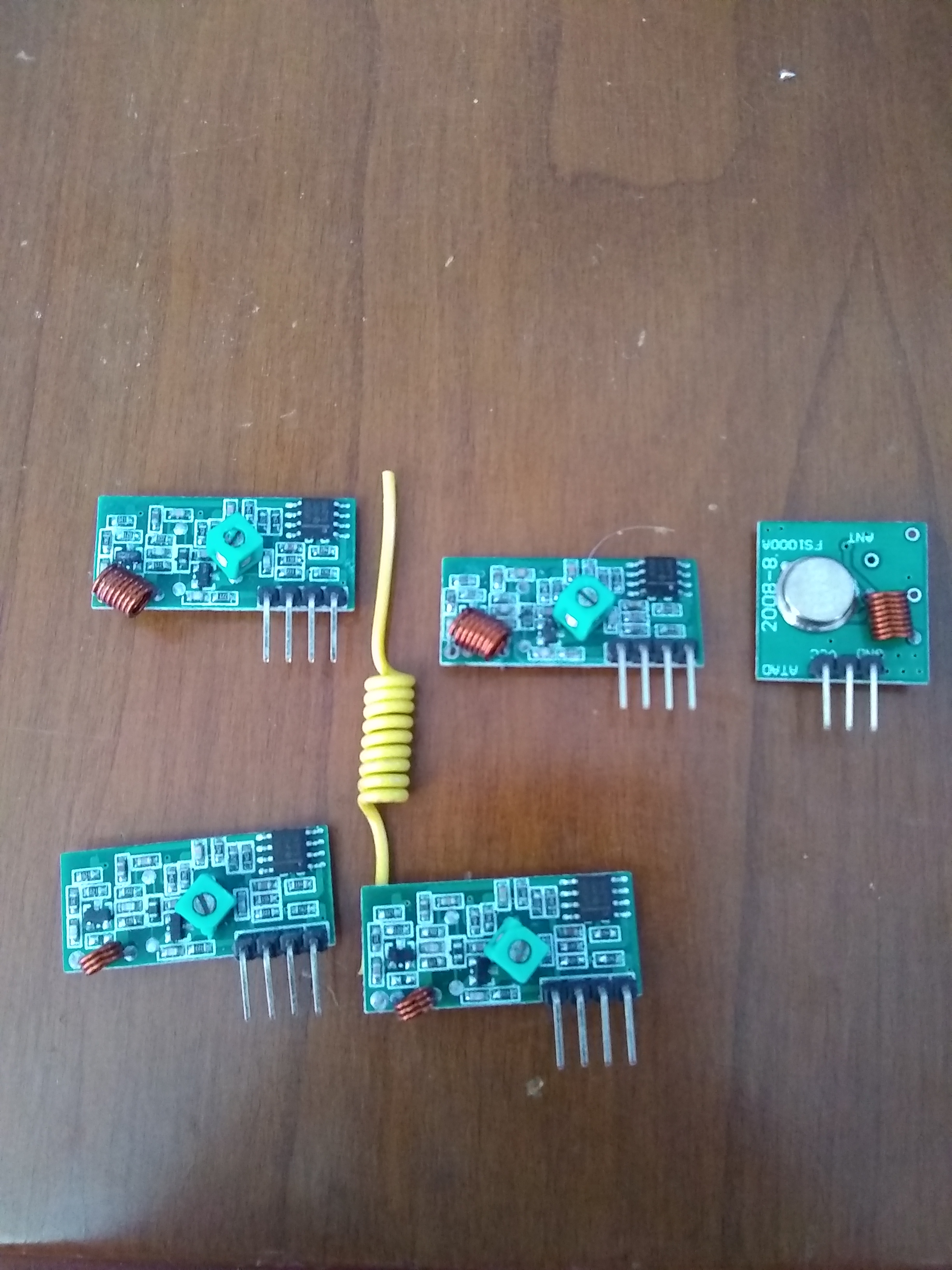
The four receivers, and a transmitter (top right). You can see that the inductive coil on the top two (problematic) receivers looks suspiciously like the one installed on the transmitter. This was taken after attaching my antenna to one of the correctly made receivers and testing.
Once I connected an antenna (see https://www.instructables.com/id/433-MHz-Coil-loaded-antenna/) to one of the properly made receivers, my reception increased from a yard to maybe 30 feet, and also gave me the capability to receive signal through an exterior wall which is what I really wanted.
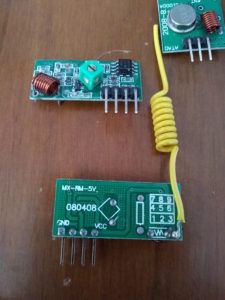
Close-up of the properly made receiver with the antenna attached, with an improperly made receiver above.
I know this is an old article but somebody may still want to play with those. The transmitter you show has a 3 turn coil missing above the 8 turn coil.The receivers you had were for 2 different frequencies and for full sensitivity should have a 2.2uh choke installed where the resistor is marked on the back. Whoever made sold them are selling rejects that were either made by the thousands or are still made that way today as I have seen the same defective units sold today.
https://vk4ghz.com/fs1000a-433-mhz-transmitter-l2-missing/
This is were you find a schematic of the transmitter.
Comment by John Cunliffe — November 30, 2020 @ 10:30 pm
Hi there! I had a same issue today! All the problems comes from the power supply!!!! Tried many antennas…..the results were not that good. Finally just added a small antenna(https://i.stack.imgur.com/WXu5k.png) and used an adapter(9V from my router) connected to the jack for power supply of the Arduino Uno board NOT THE USB one….guess what – the range is just perfect!!!
Comment by Bigi — December 26, 2020 @ 2:15 pm