Note: This document is a work in progress and will change frequently. It’s my kegerator scratch pad if you like.
I got at least a portion of the components for my keezer setup this afternoon, along with a 40 gallon boil kettle and several carboys. Now we can really make beer, as well as some mead and perhaps some wine in the near future as well. Making a few notes on the buildout for the keezer. I don’t plan to complete a final build just yet as I’m only doing four pin lock kegs at present, but I don’t want to have to replace core components such as tubing when I upgrade. I figure it’s best to just start with fresh o-rings and gaskets in the kegs from the outset.
- Kegerator
- Freezer
- Collar
- perlick faucets
- shanks
- tailpiece
- tailpiece washer
- beer nut
- gas tube, 5/16″
- beer tube
- bev-seal ultra 235 tubing… probably 3/16″ ID per forum thread note below (plus clamps, etc.)
- Accuflex Bev-Seal Ultra 235, 3/16″ID
- Oetiker clamp
- size 8.7 – does NOT fit over barbed fitting in BevSeal Ultra 3/16!
- size #10.5 – 13/32″
- size #12.3 – 15/32″ – fits CHI 1/4″ high pressure CO2 Hose
- Barb to flare fitting (1/4″ FFL – female flare – to 3/16″ID barb)
- Brewmasters Warehouse $1.30 (24-Jan-14, awaiting confirmation of barb ID, and I should also verify that it’s a flare fitting and not NPT)
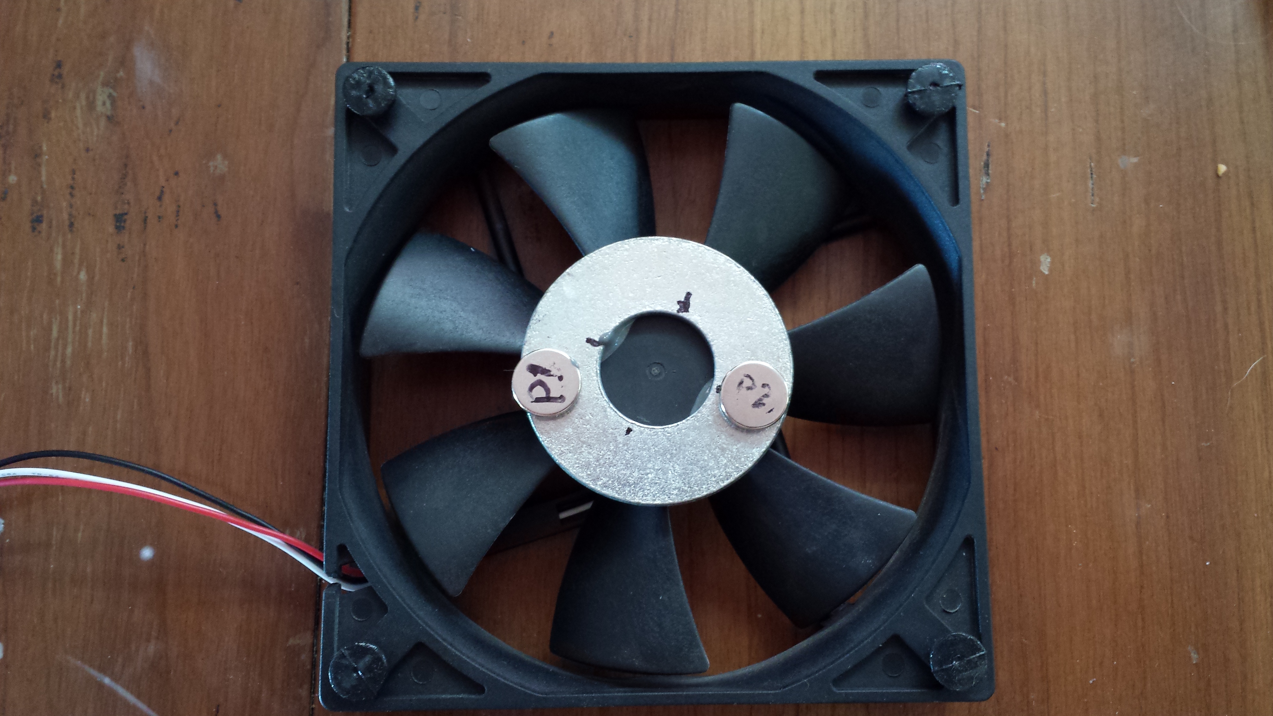
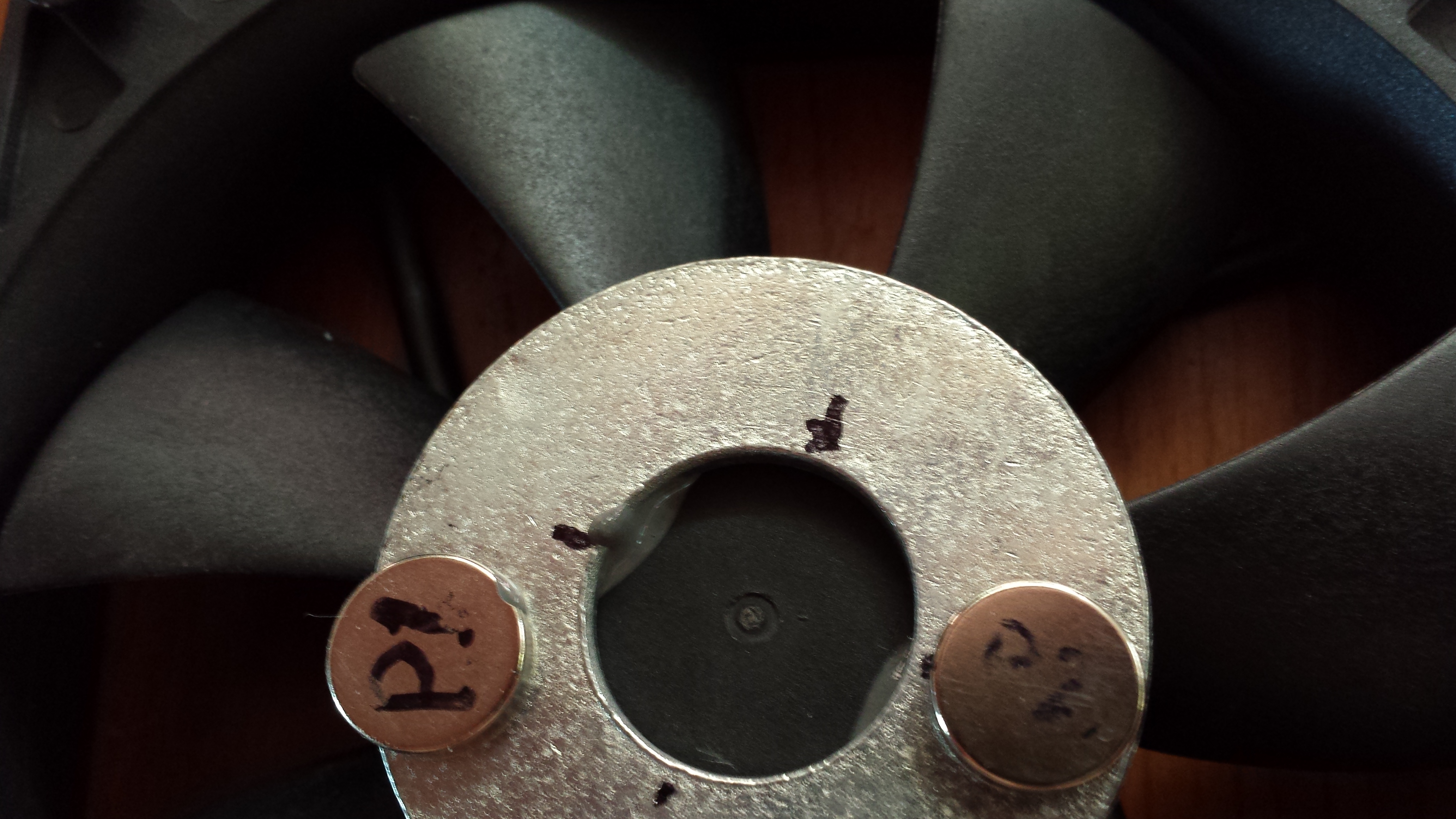
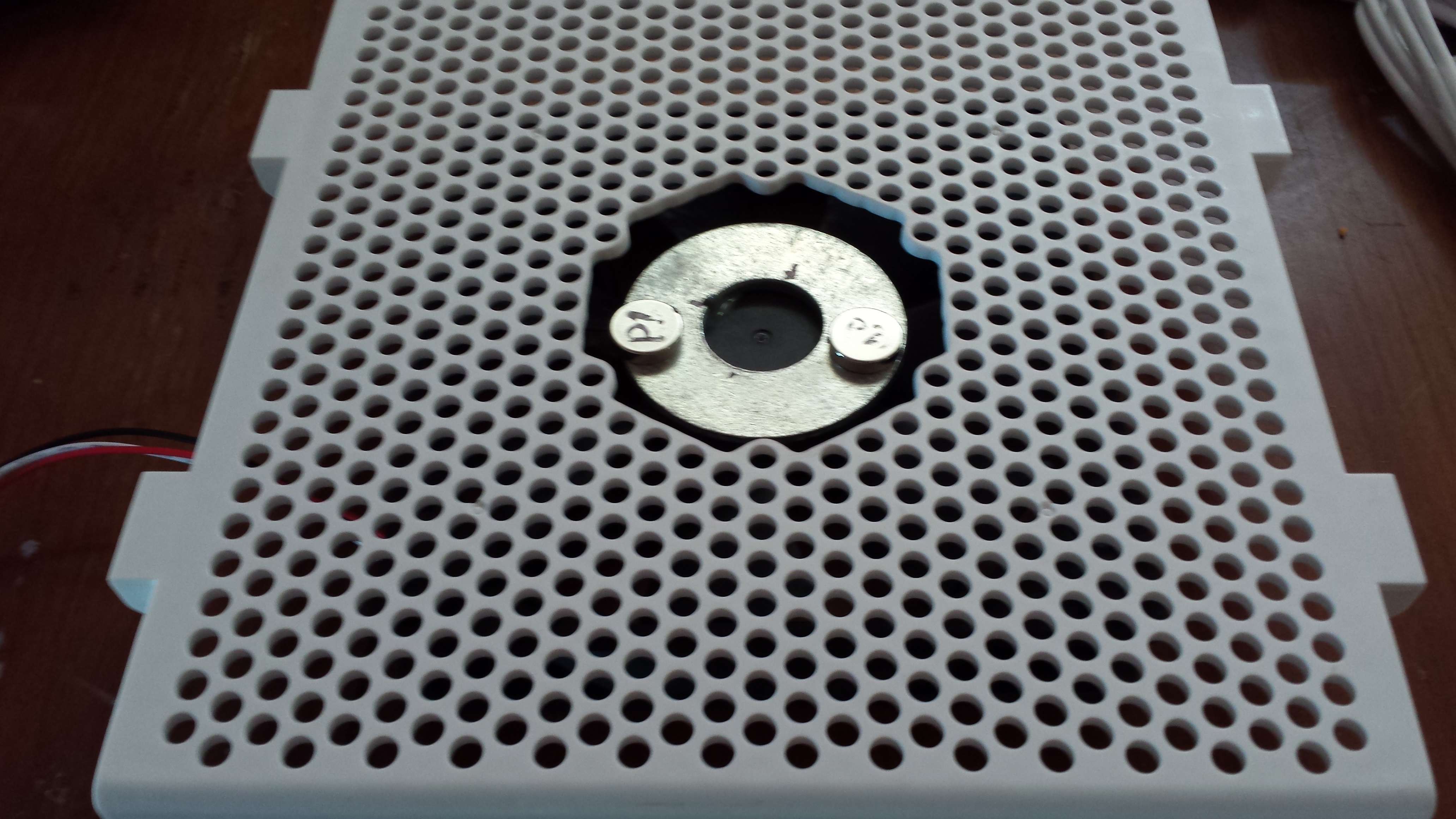
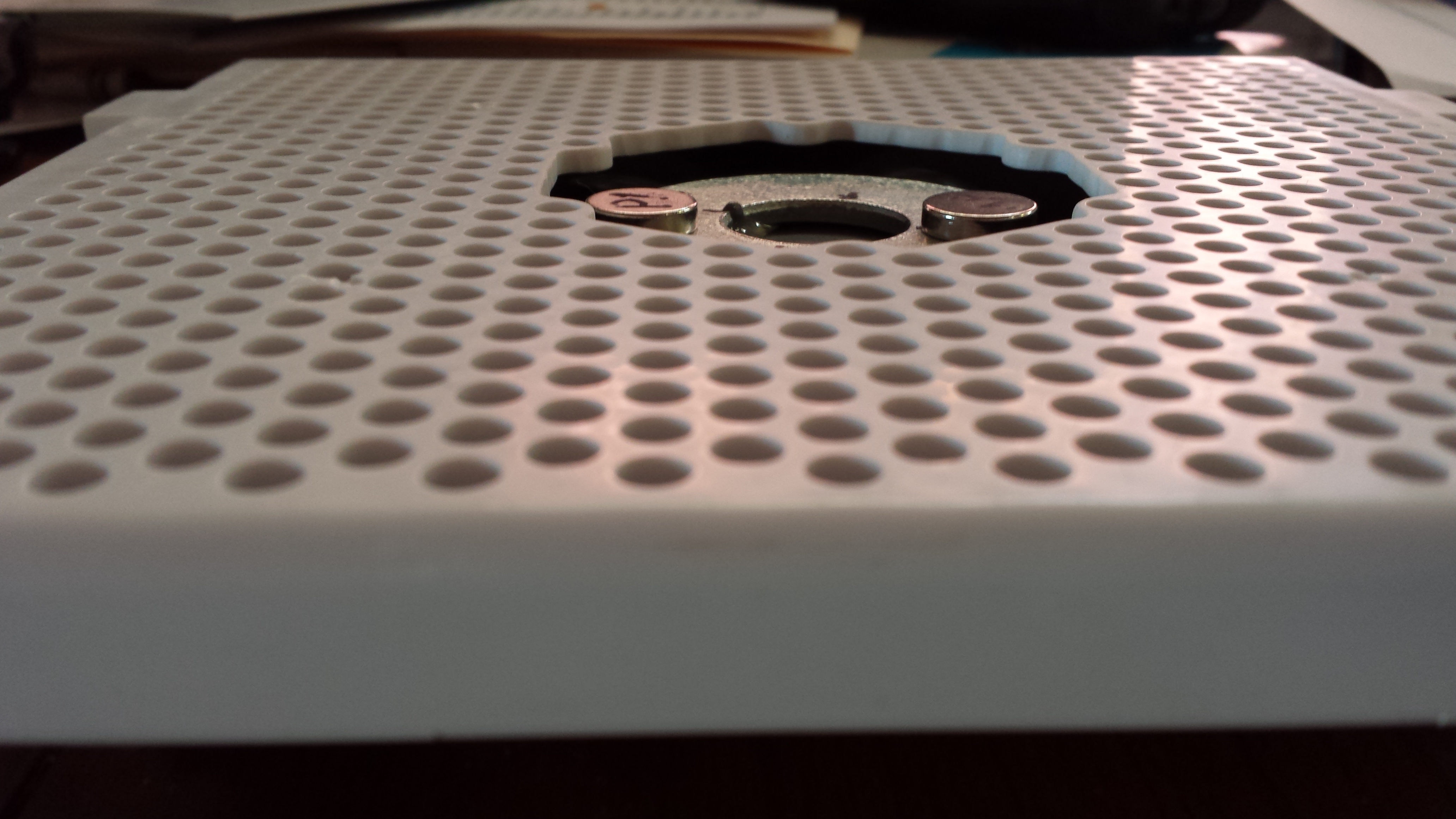
- 120mm computer case fan for circulation $4.99
- dip tube o-rings Buna-N 109, 5/16″ID 1/2″OD 3/32″ width
- Qty 100 ordered from Amazon 2014-Jan-10 (source/recommendation HomebrewFinds.com Amazon add-on list)
- Northern Brewer Dip tube O-ring Type B, SKU K120, $.50
- Adventures in Homebrewing O-ring set for Cornelius pin-lock (lid, 2 post, 2 dip tube), part 99-2641B, $2.99
- pin post o-rings Buna-N 111
- Qty 100 ordered from Amazon 2014-Jan-10 (source/recommendation HomebrewFinds.com Amazon add-on list)
- chicompany.net pin-lock post O-rings, $.25 ea or $16.99 per 100
- Northern Brewer pin lock plug/post O-ring – black, SKU K118, $.99
- Adventures in Homebrewing O-ring set for Cornelius pin-lock (lid, 2 post, 2 dip tube), part 99-2641B, $2.99
- cornelius keg lid o-rings Buna-N 417
- Qty 10 ordered from Amazon 2014-Jan-10 (source/recommendation HomebrewFinds.com Amazon add-on list)
- chicompany.net Oval gasket, $84.99/100
- Adventures in Homebrewing Cornelius lid O-ring, part 91-2407, $1.99
- Adventures in Homebrewing O-ring set for Cornelius pin-lock (lid, 2 post, 2 dip tube), part 99-2641B, $2.99
- pin lock poppet o-rings (?)
- pin lock connectors, ~6 sets (have 2 sets)
- North American (Sanke) D System (NADS) coupler
- CO2 tank, probably 20lb
- (Purchased 26-Jan-14) eBay, $88.00 shipped!
- Exchanged at local Linweld with no problems; $26.22 including tax.
- Beverage Elements recertified $67.95 plus shipping (est $38)
- Micromatic (only 15lb) $89.00
- regulator
- manifold
- temperature controller (STC1000)
- ordered from Amazon 2014-Jan-10
- disconnect for temperature controller sensor probe
- Radio Shack (both of the following)
- Note: I have one of each of the above still available, and would consider selling.
- part/o-ring lube
- picnic tap
- faucet wrench
- dehumidifier
- pin lock posts
-
Article that led me to Bev-Seal Ultra 235.
Forum thread discussing/recommending use of 3/16″ Bev-Seal to reduce foaming, especially on shorter runs and recommendations on how to install.
Dip tube insert that allows reduction of serving pressure or line length
http://www.mcmaster.com/#74695a58/=qe6iu6, discovered from thread at http://www.homebrewtalk.com/f35/cure-your-short-hose-troubles-100151/index2.html. Isopropyl alcohol and/or boiling only to clean due to delryn decomposition (highlighted in several posts in the thread).
BYO article on balancing your distribution system. And another post from a fluid mechanics expert that points the way if I decide to get into the technical details and calculations for accurate determination of hose lengths, though I’m not sure how readily the information about the Bev-Seal Ultra resistance characteristics will be, and as someone else had mentioned it’s also possible that variance/inaccuracy in our regulators could cause a lot of the variations people seem to experience with line lengths.
Adventures in Homebrewing
Complete 4-keg pinlock system (excluding kegs and tank) for $382.99; can add 10# tank for $60. Part/item 4470-7, $382.99
O-rings, 5 sets, post and dip tube, $4.50 shipped – http://www.ebay.com/itm/5-Homebrew-Beer-BALL-or-PIN-LOCK-Cornelius-Keg-Post-Dip-Tube-RED-O-ring-Kits-/151173485689?pt=LH_DefaultDomain_0&hash=item2332a45479
Good deal on set of ten gasket/o-ring kits for ball/pin lock on eBay, added to watch list; somewhat up in the air as I understand pin lock o-rings to be slightly thicker than ball lock.
Freezer Layout and Dimensions for Kegerator/Keezer
Measurements
- Front to back (outside, corners): 21 11/16″
- Front to back (outside, middle): 21 5/8″
- End to end (outside, corners): 41 1/4″
- End to end (outside, middle): 41 3/16
- Front to back (inside, inner lip): 16 1/4″
- End to end (inside, inner lip): 35 13/16″
- Front to back (inside, outer/upper lip): 17 9/16″
- End to end (inside, outer/upper lip): 37 1/8″
- Lip width (inner): 7/16″
- Lip width (outer/upper): 2″
- Hump width: 11 1/8″
- Non-hump width: 24 7/8″
- Hump depth (top of hump to top of inner lip): 18 11/16″
- Non-hump depth (bottom of main compartment to top of inner lip): 28 3/4″
- Body front to back (outside): 21 7/16″
- Body width end to end (outside): 41″
- Lid front to back (outside): 21 1/2″
- Lid width end to end (outside): 41 1/16″
- Lid height: 1 1/2″
- Top of lid to top of outer lip: 2″
Open Space Measurements
Measurements of remaining open space with a fill equivalent to six pinlock kegs.
- Main compartment with 4 kegs, open corner at end (smallest measurement): 5″
- Main compartment with 4 kegs, open corner next to hump (smallest measurement): 5 1/2″
- Hump open space at corner with six kegs (approximated), maximum: 6 1/4″ x 7 1/4″
- Top of keg in main compartment to top of inner collar/lip: 6 1/2″
- Top of keg on hump to top of outer lip (i.e., minimum collar): 3″
Build Process
Temperature Controller
31-Jan-14
After a false start getting an old work junction box that was only two gang, and both too narrow and too deep for the way I wanted to set up my temperature control unit, I was able to get it mostly put together on Friday (31-Jan-14). I still didn’t get exactly what I wanted, but I was able to make it work. Ideally I wanted a faceplate with a rectangular outlet opening on one end and the other two spaces blank. Unfortunately they didn’t have such a thing at the local big box store, so I got a three gang cover with a rectangle on one end and two regular switch outlets in the other spaces. I chose this option so I wouldn’t leave any random holes or partial cutouts on the faceplate when I made the hole to mount the controller; its mounting hole will consume both of the switch cutouts completely.
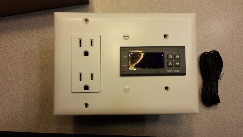
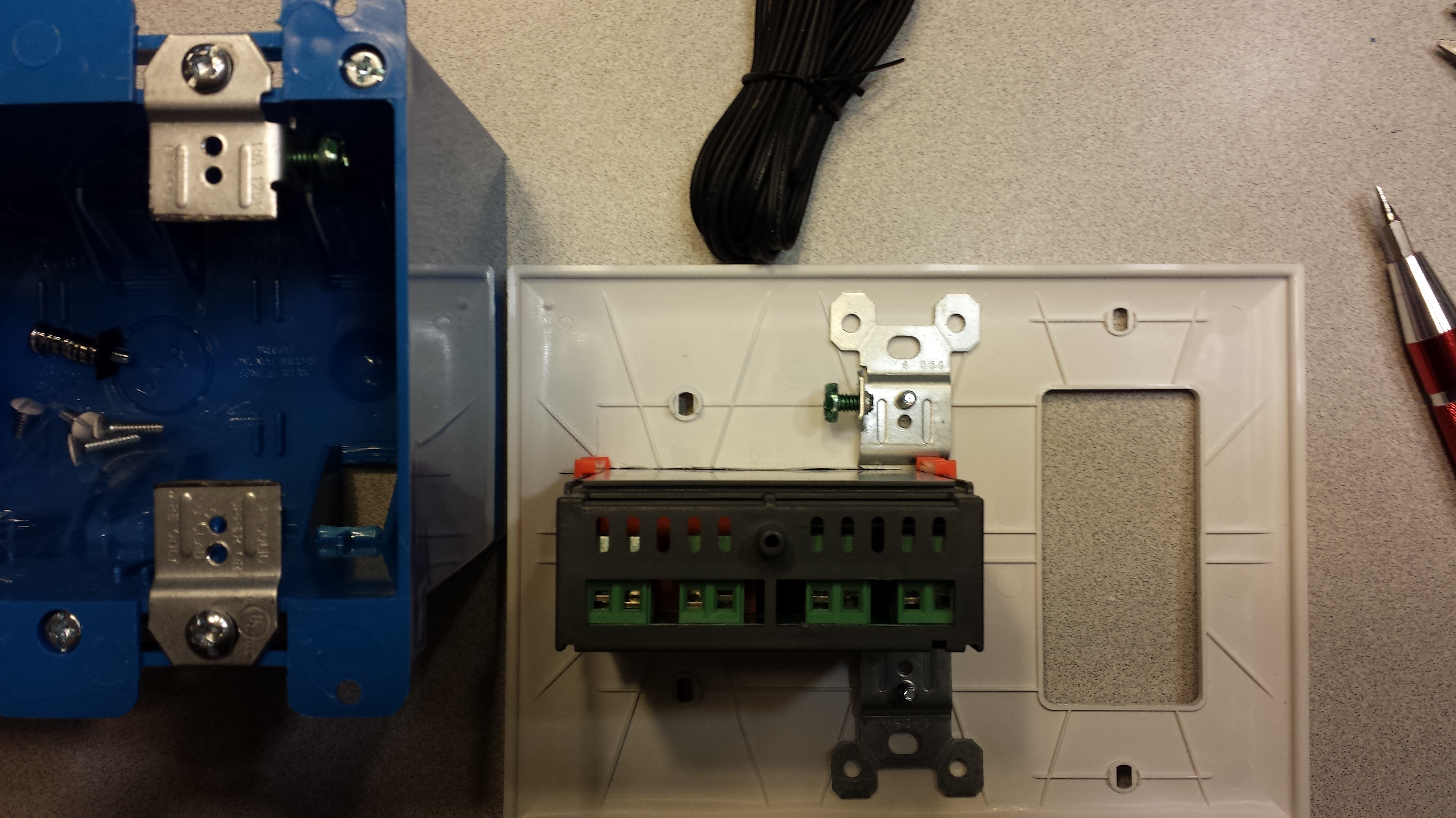
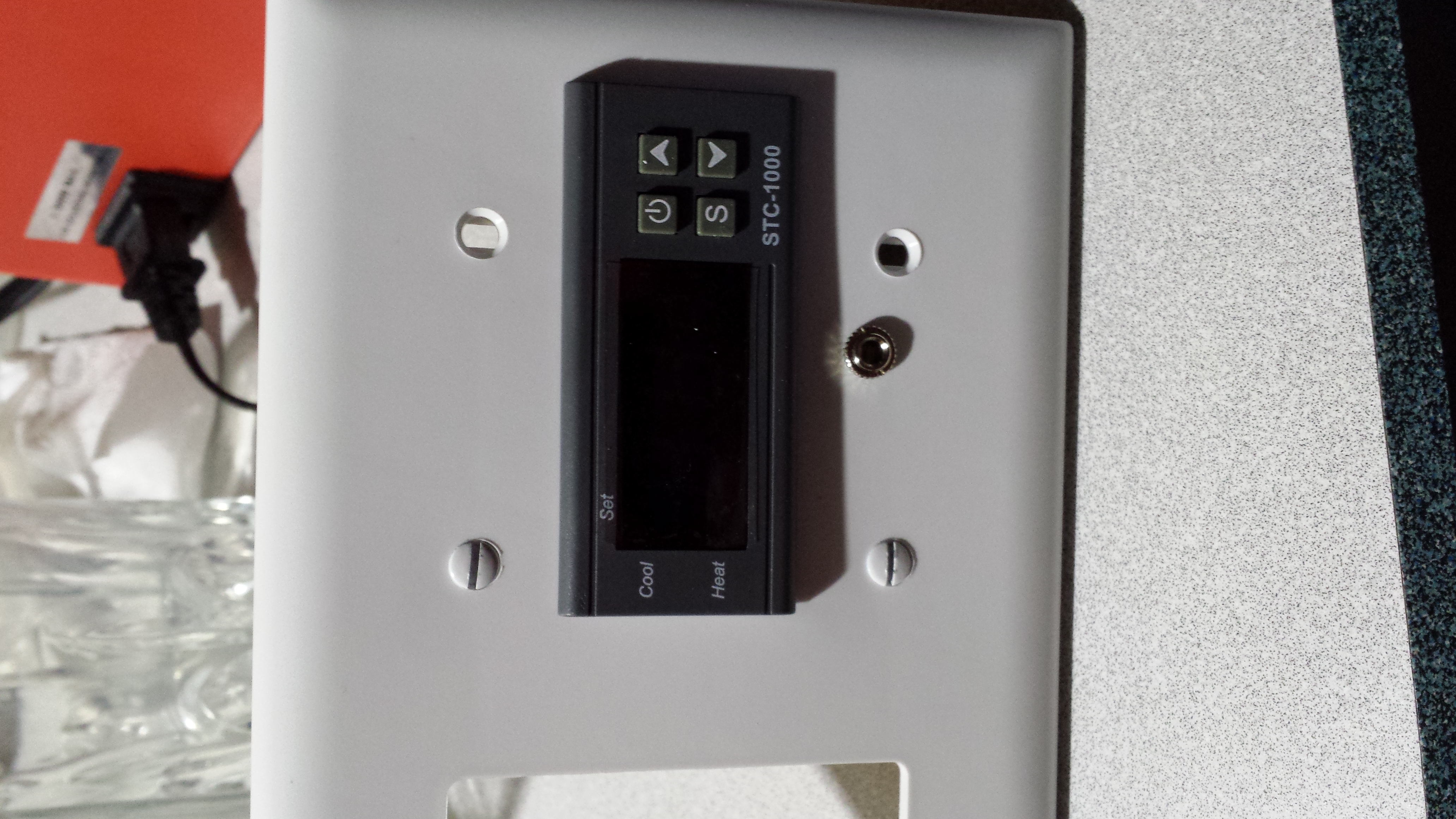
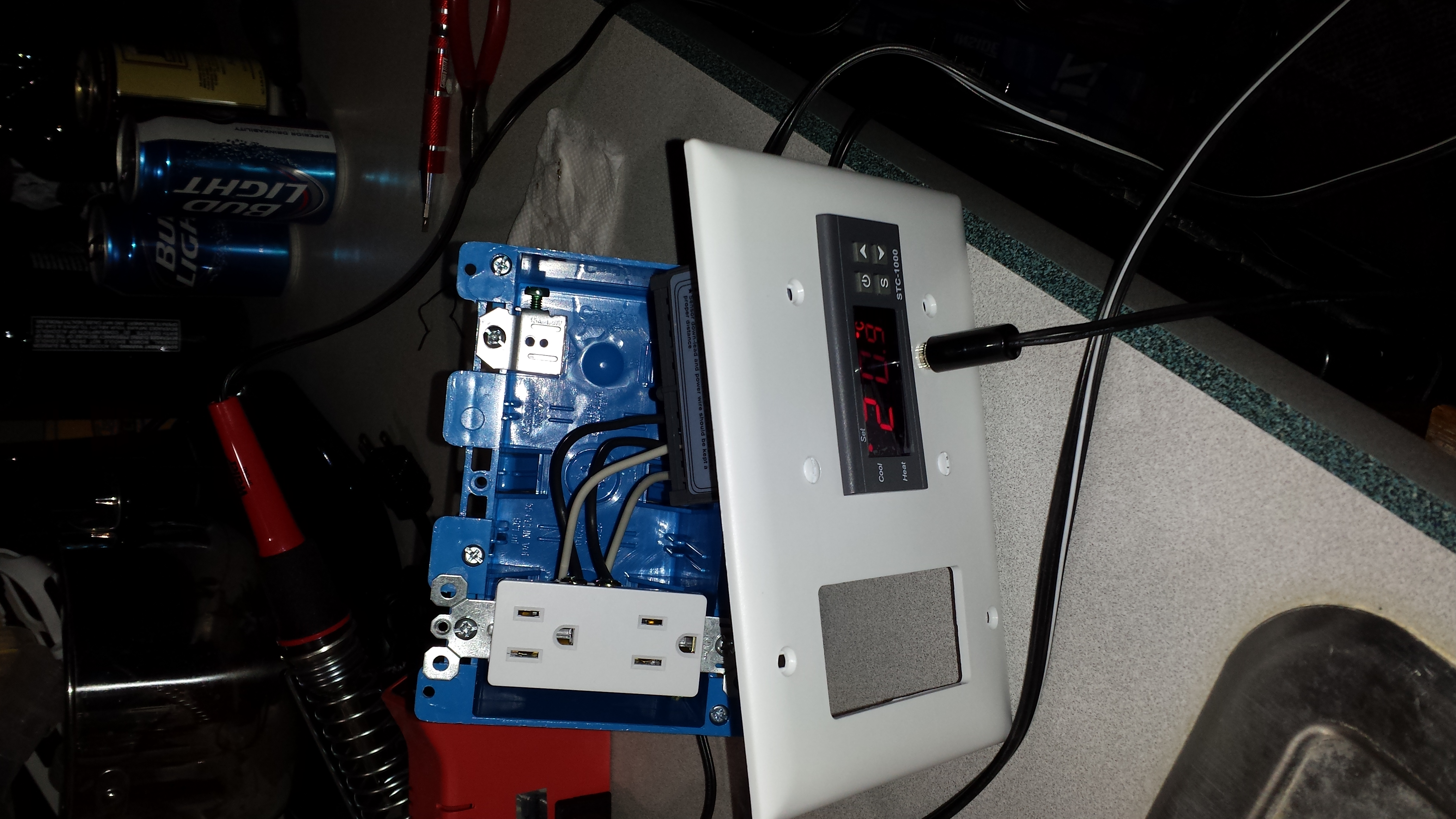
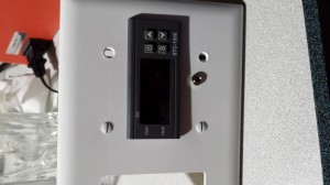
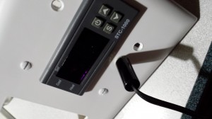
The keezer temperature controller in a “test fit” configuration. I still need to add a connector for the actual temperature sensor, and I think I’ll get a 1/8″ phono jack and plug to accommodate this.
You may or may not have noticed that the mounting holes for electrical cover plates vary with the component installed behind them. The mount points in the junction box/gang itself are consistent, as all devices mount into them; this is why I wanted the layout I did, so that the space where I make the cutout for the temperature controller itself will mount directly to the box and the outlet space will attach to the outlet. They don’t appear to make (or the store didn’t have) a mounting assembly that I could use to adapt the gang box mounting holes to fit the narrower spacing of the light switch holes, so I bought a pair of the cheapest generic light switches they had ($.54 each) and removed the actual switch part, then slightly modified them to make two different types of attachment points (see picture below).

6-Feb-14
After picking up a few additional parts from Radio Shack to make the temperature sensor modular/disconnectable, I did some wiring this evening. I can hear the controller relays kicking, but unfortunately it doesn’t appear to be firing the heating or cooling outlets, so I have some troubleshooting to do.
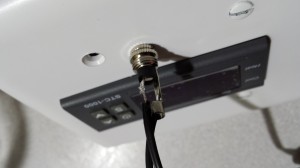
1/8″ stereo jack to allow quick disconnect for temperature sensor. I could have used a mono to match the plug, but Radio Shack didn’t have one.
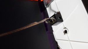
Soldering the 1/8″ male mono plug.
The solder job was better before I had to remove and redo it because I forgot to put the housing on the wires first.

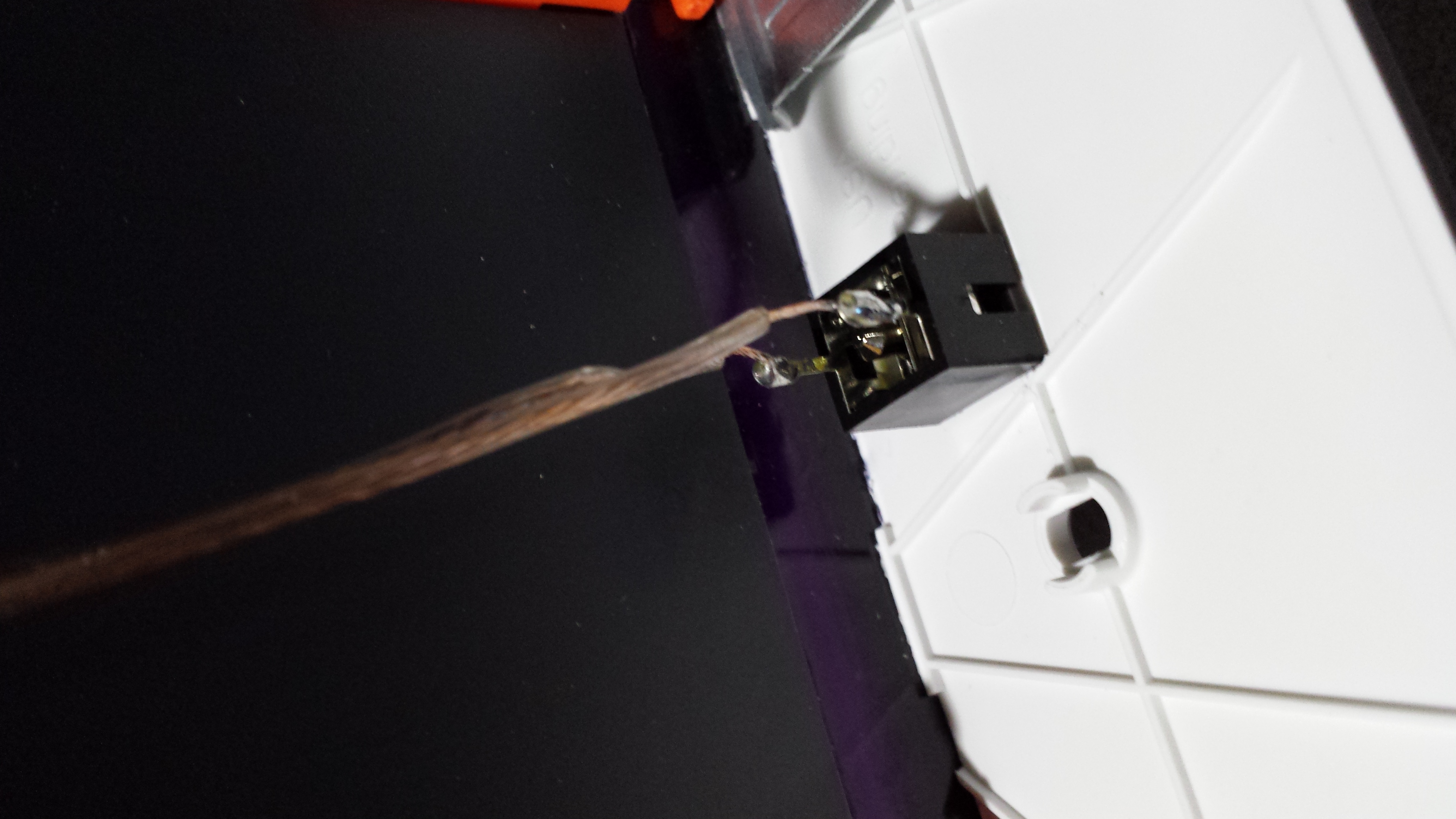
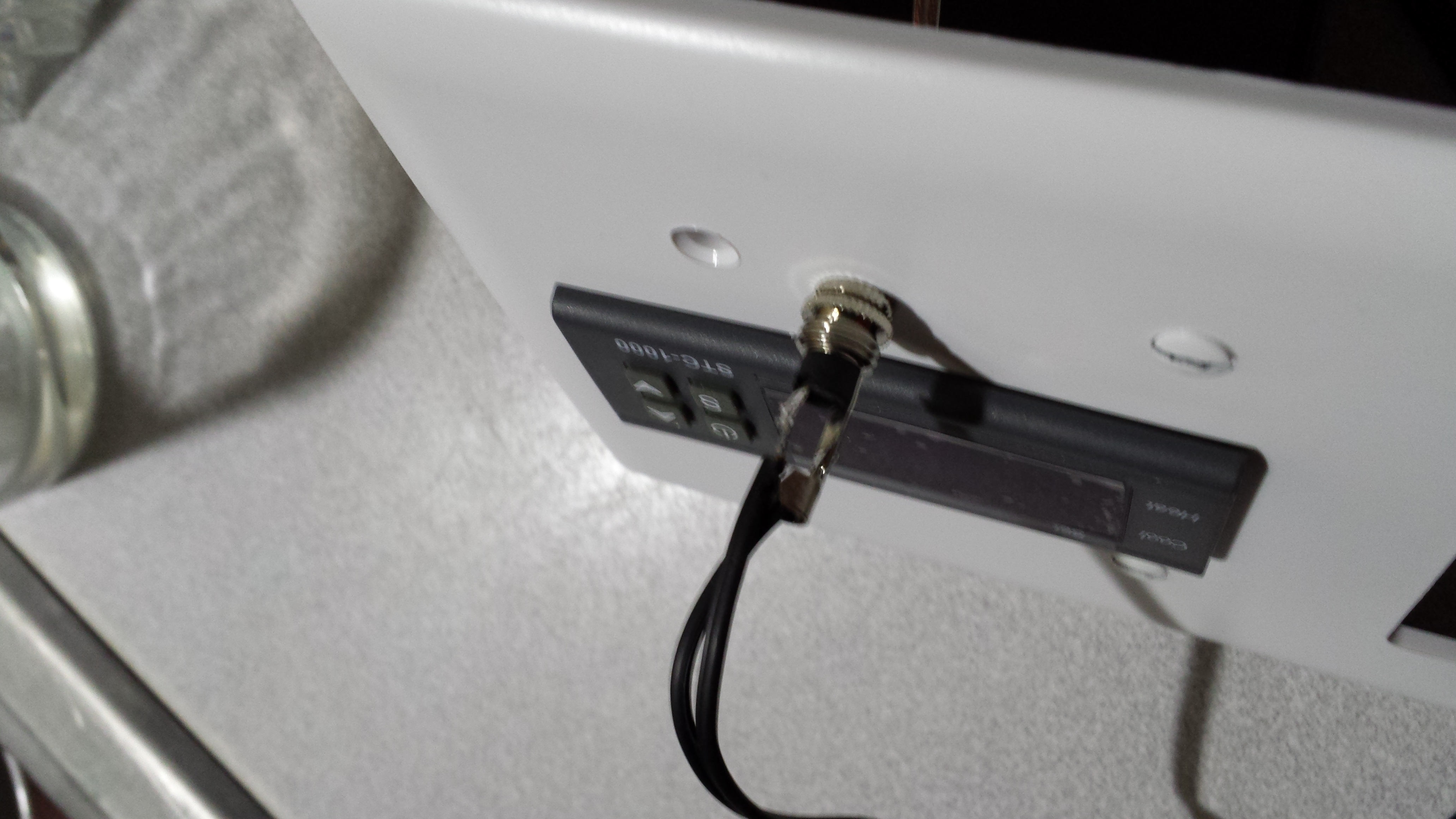
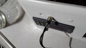
Temperature sensor disconnect in place and wired to the relay.
Front view of the finished temperature sensor disconnect.
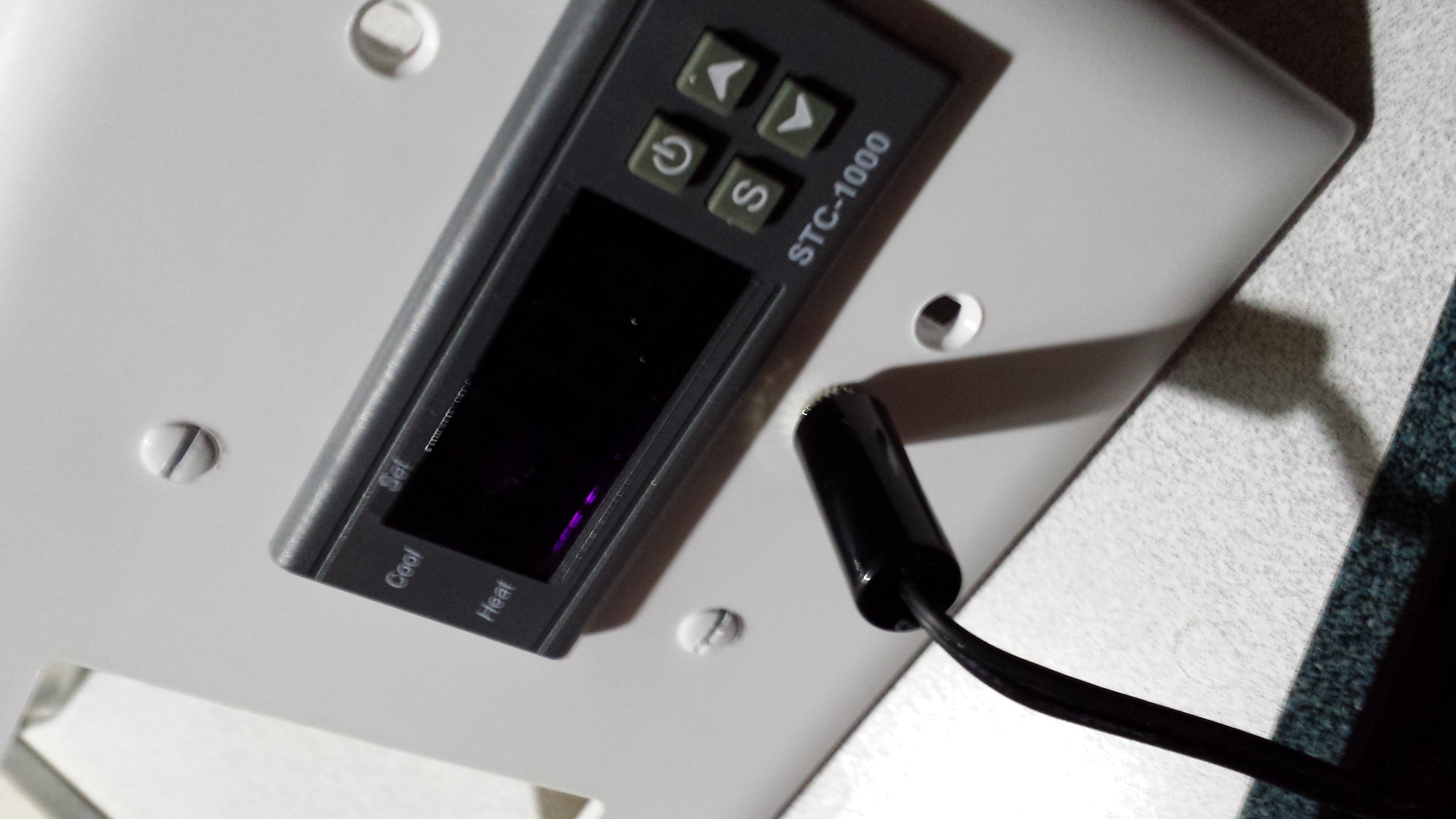
Temperature sensor disconnect with sensor attached.
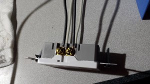
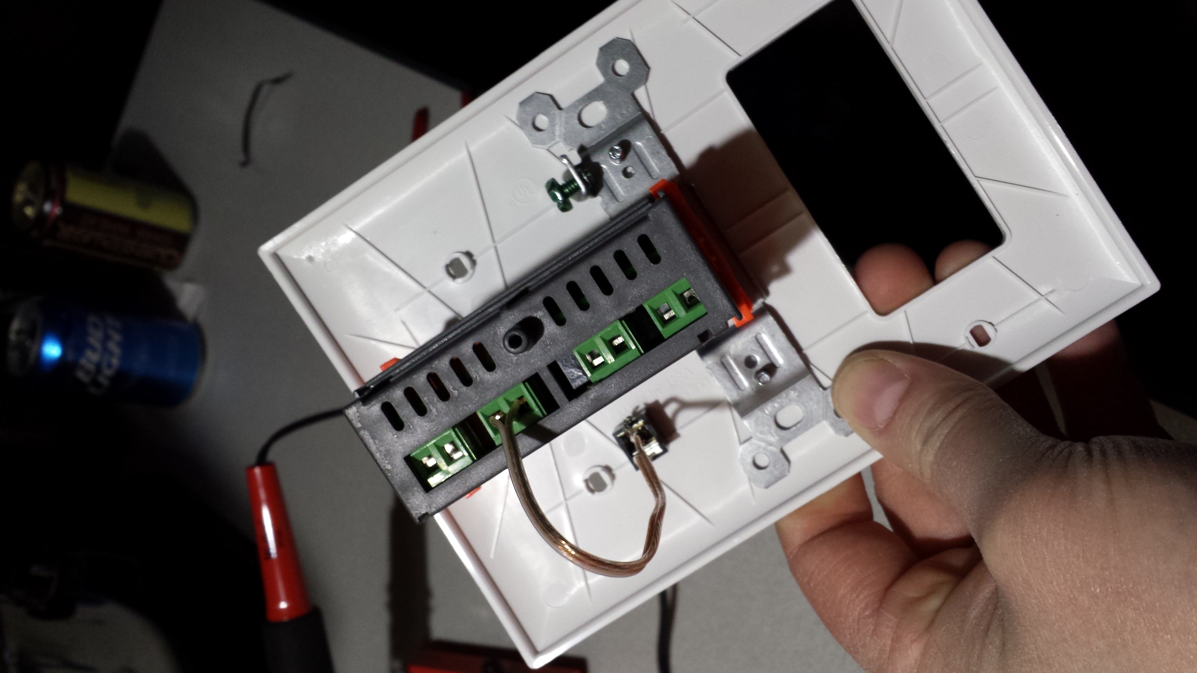
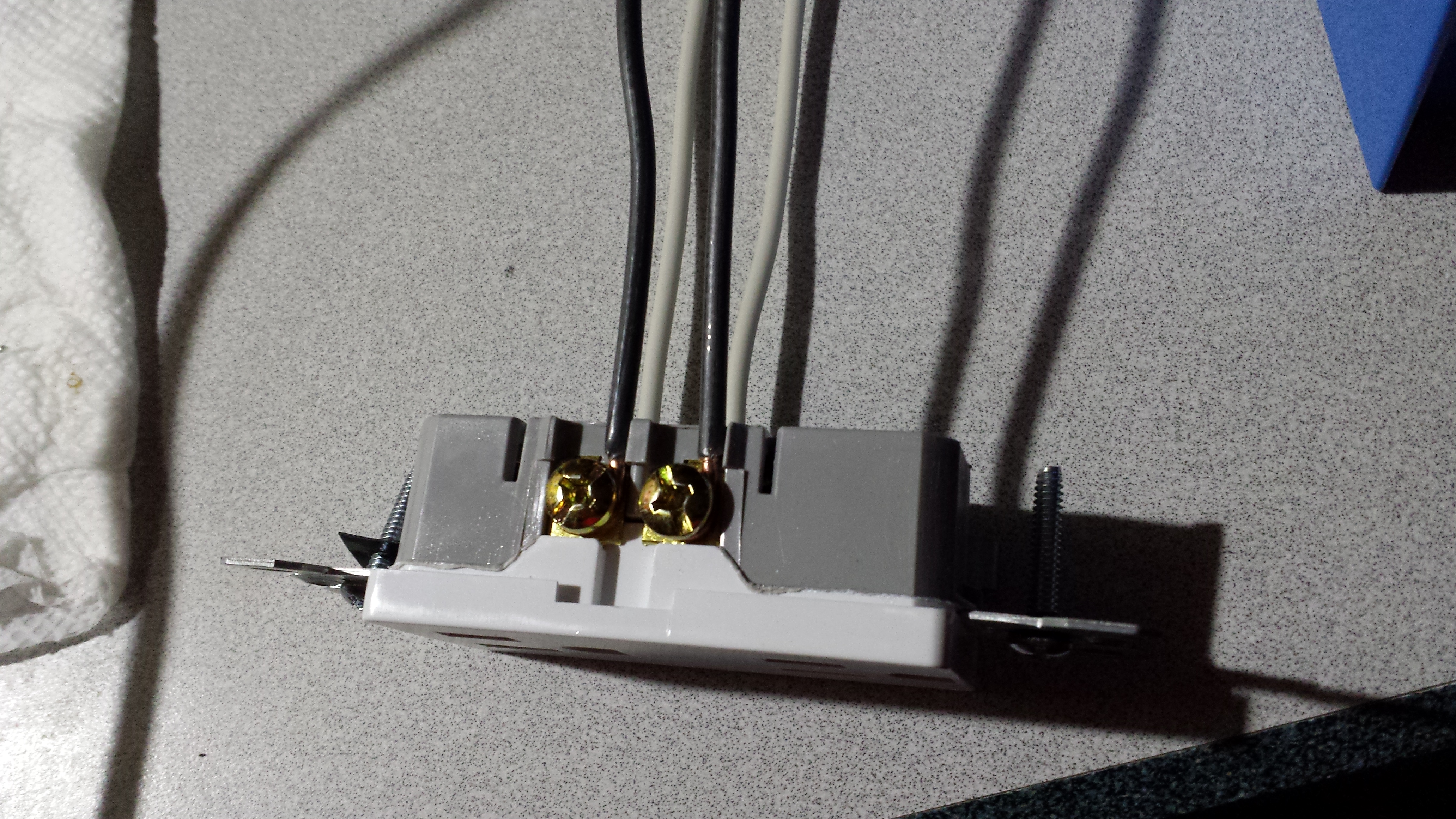
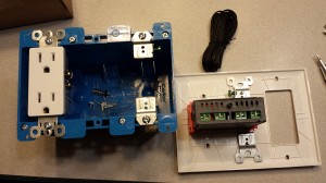
Wiring the outlet. Note the split outlets (the removable bridge between the screws is… removed).

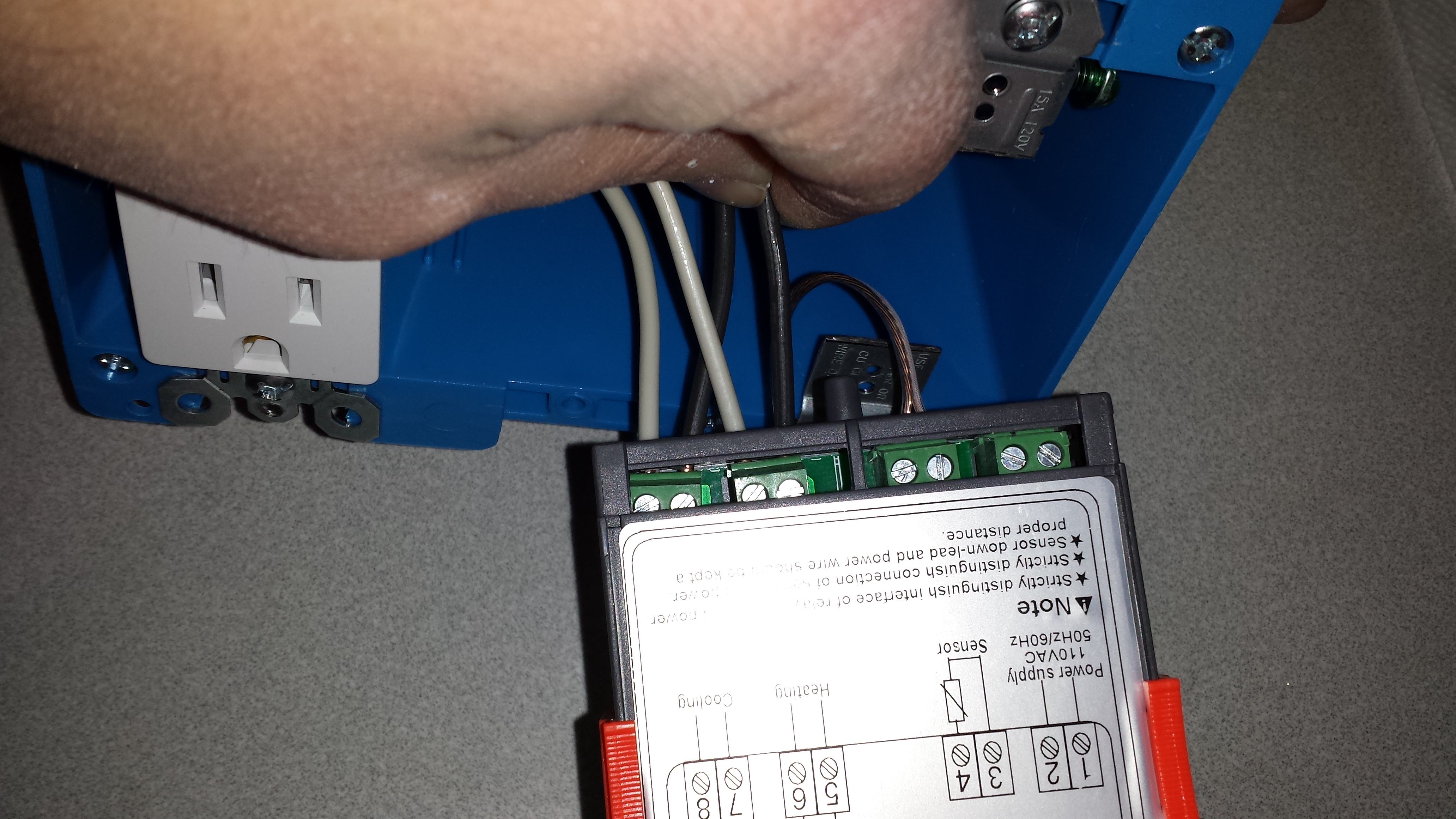
Wiring the outlets into the STC-1000.

Hacked together for a test run with a pigtail I keep on hand.

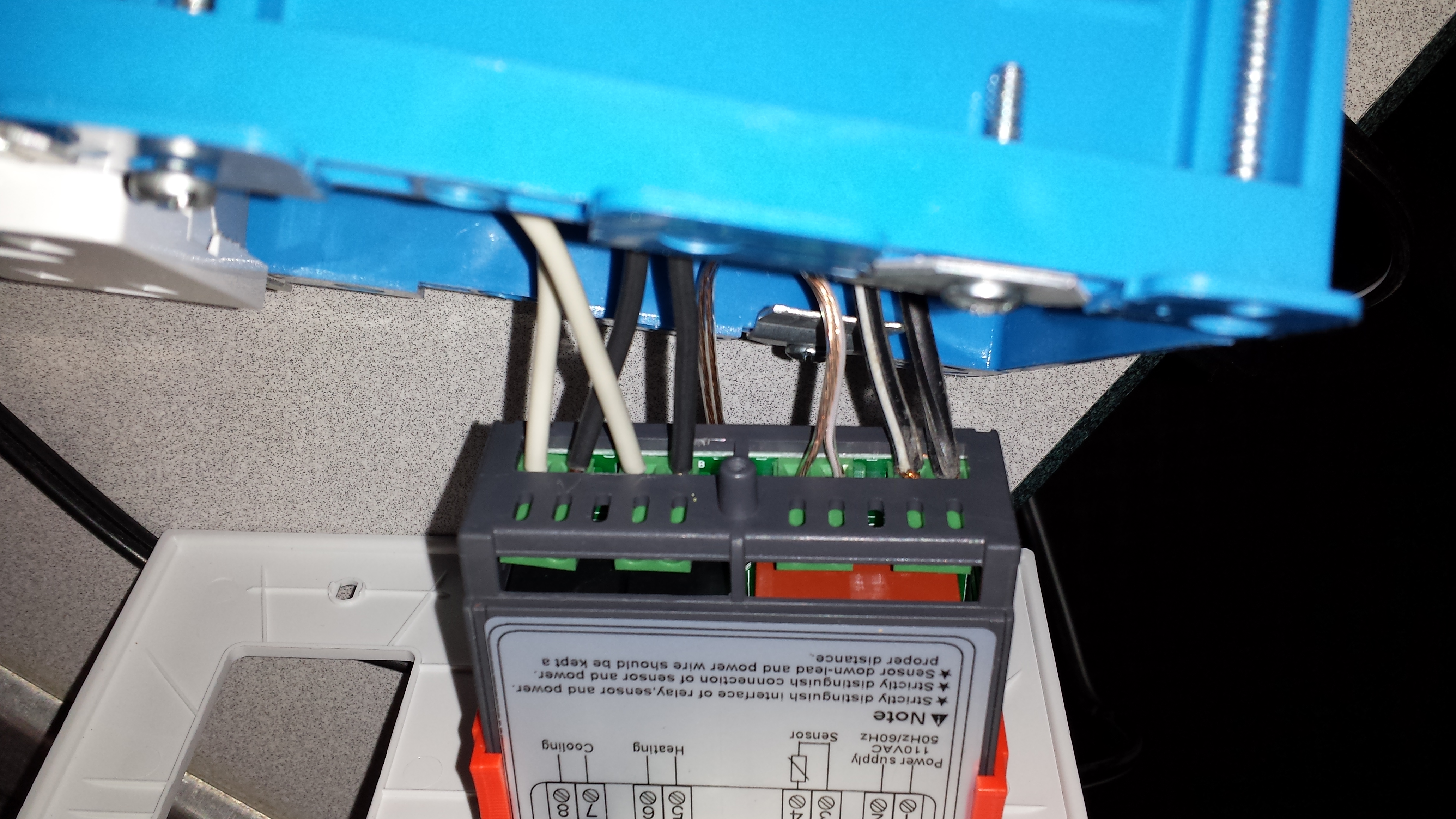
Final view of the connections. Unfortunately not working, but I think it’s an issue with the controler.