Landis Vinchattle An aggregation.

February 12, 2014

Bray’s One Month Mead – Home Brew Forums

Filed under: Food and Drink,Links — Tags: — Landis V @ 9:38 pm

http://www.homebrewtalk.com/f30/brays-one-month-mead-429241/

After making my mead this past weekend, I still have around 12lbs of honey left.  I ran across this recipe in the past and thought I had bookmarked it; I hadn’t.  Doing so now, as this seems like another interesting possibility to try out with my remaining honey.

January 28, 2014

Electric Heat Stick Brew Kettle Plan

Filed under: Electronics,Fabrication,Hobby Engineering,Links,To Buy — Tags: — Landis V @ 6:12 pm

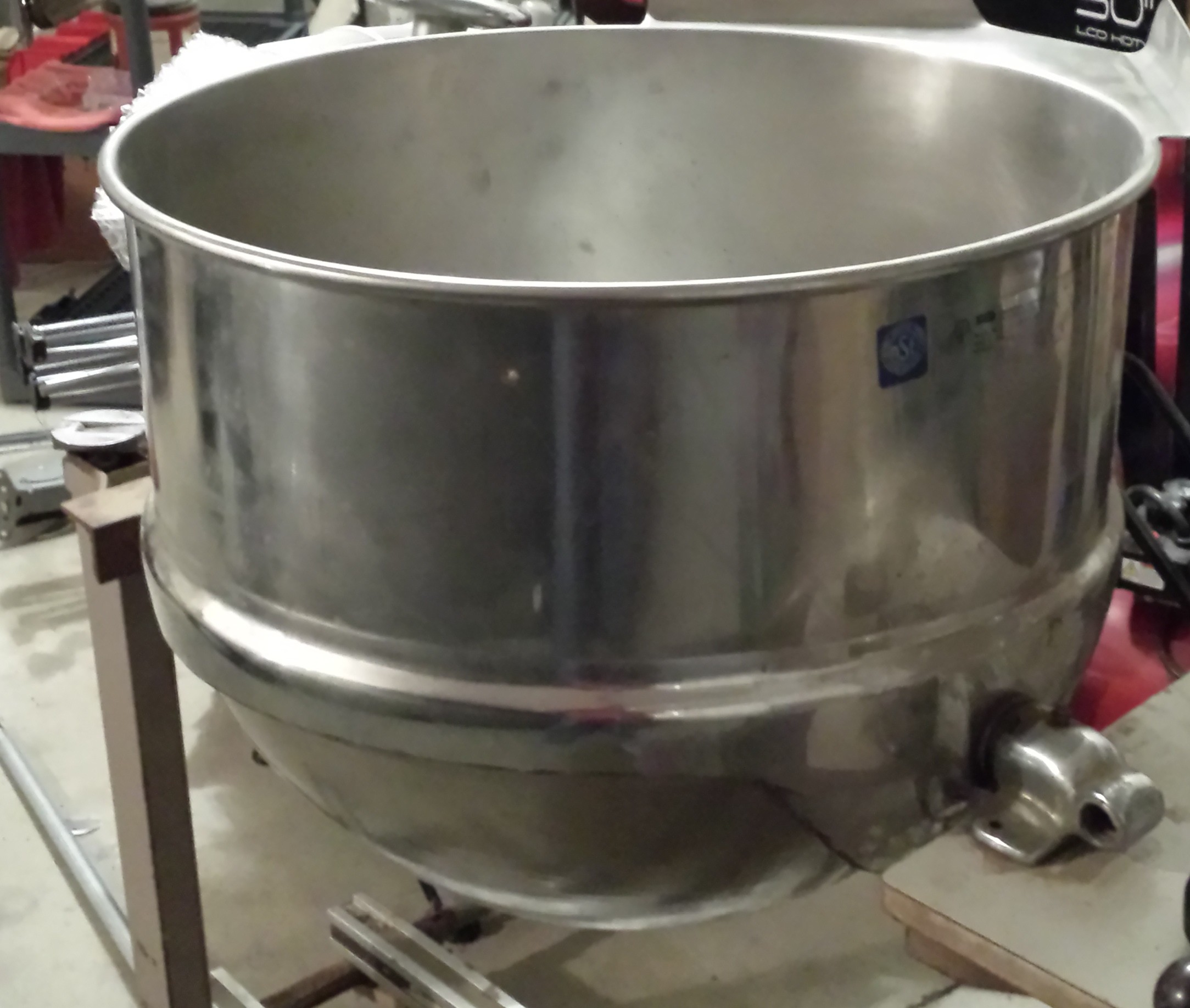
20140104_223859I mentioned in a recent post that I had come into the opportunity to use a nice size stainless steel (formerly steam jacketed) pot as a brew kettle.  My initial thought was that I needed to purchase a considerably larger propane burner with a much higher BTU output, but a friend who has recently completed an electric setup in a converted 15 gallon keg brought up the possibility of crafting a heat stick.

I was somewhat familiar with electric systems from hearing his progress as he went through the build process, but was unfamiliar with electric heat sticks.  The gist of the idea is using a heating element from an electric water heater  as the heat source for a boil kettle.  Perfect for a setup with a borrowed kettle that I don’t want to modify!

There are a number of reference articles, posts, and threads for building full electric systems with kettle-mounted elements, but brewing with heat sticks seems to be a somewhat newer trend.  Even so, there are a number of designs in existence.  The latest generally seem to use an ultra low watt density element, though there are many reports that the regular elements are perfectly suitable and don’t impact even very light lagers.  I’ve already found an element that I think will be suitable assuming I have sufficient watt output.

This post is another of my evolving “project in progress” posts, so it will change and evolve as the project moves from research, planning, and design through the build, test, and finalization phases.

Project potential part/price/location list

Stainless build options/discussion threads

Electrical and Wiring

Abandoned Ideas

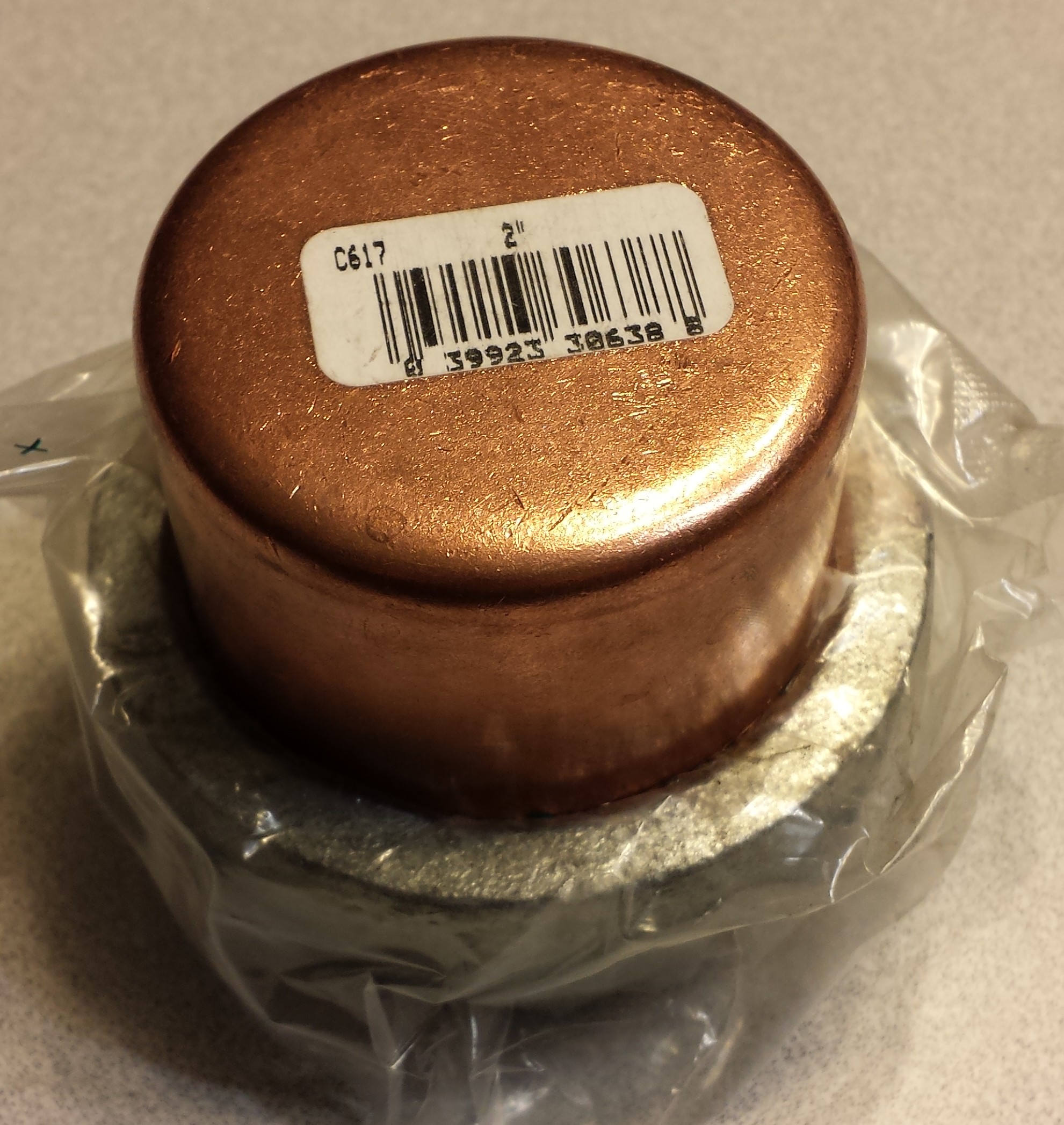
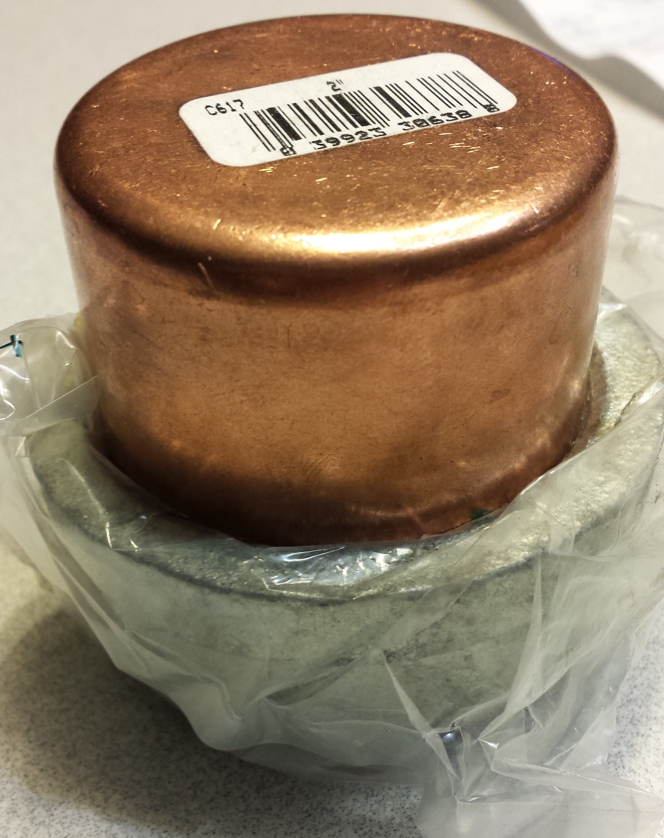
2″ Copper Endcap Threaded Into 2″ Stainless Steel Female Cap

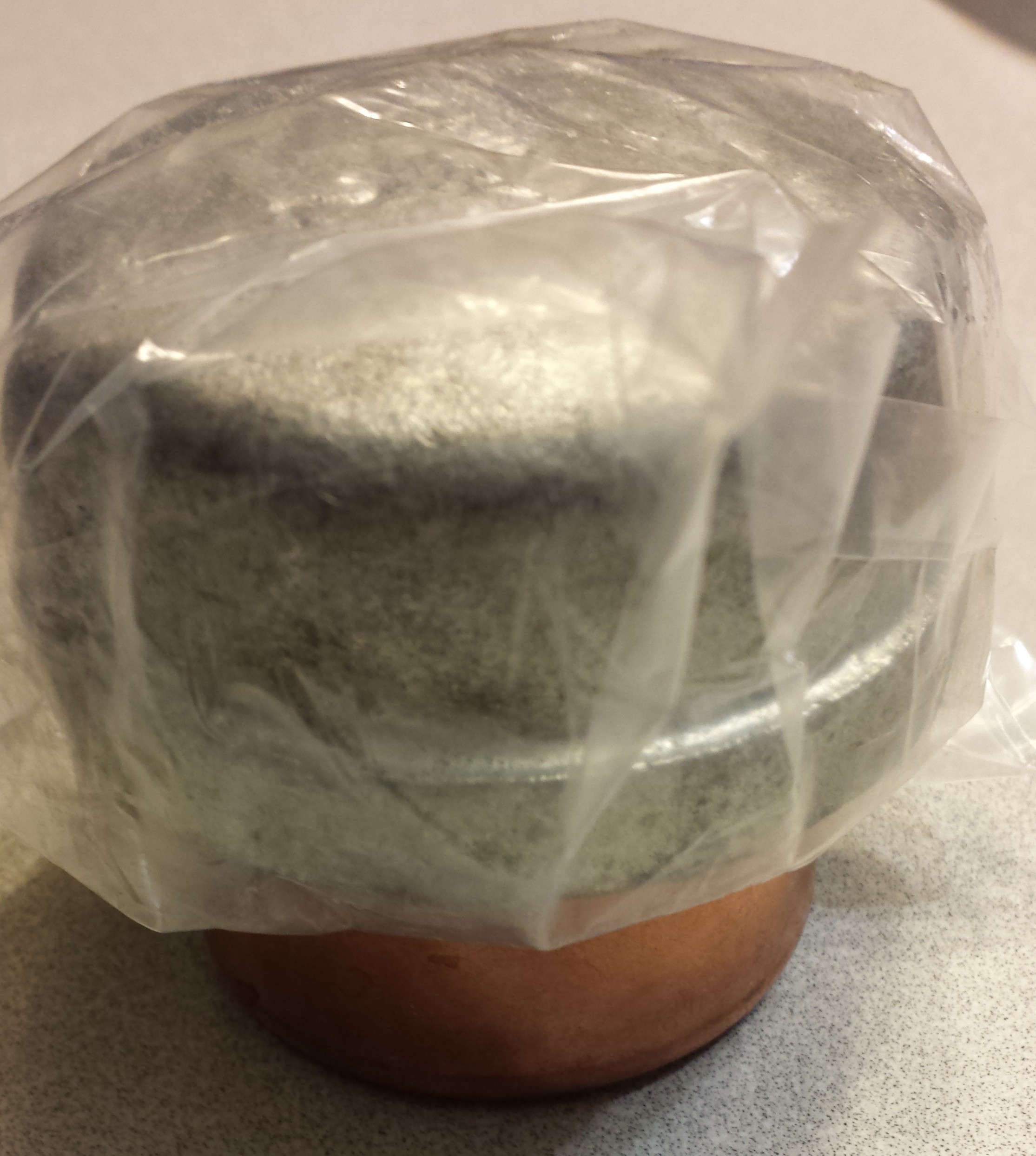
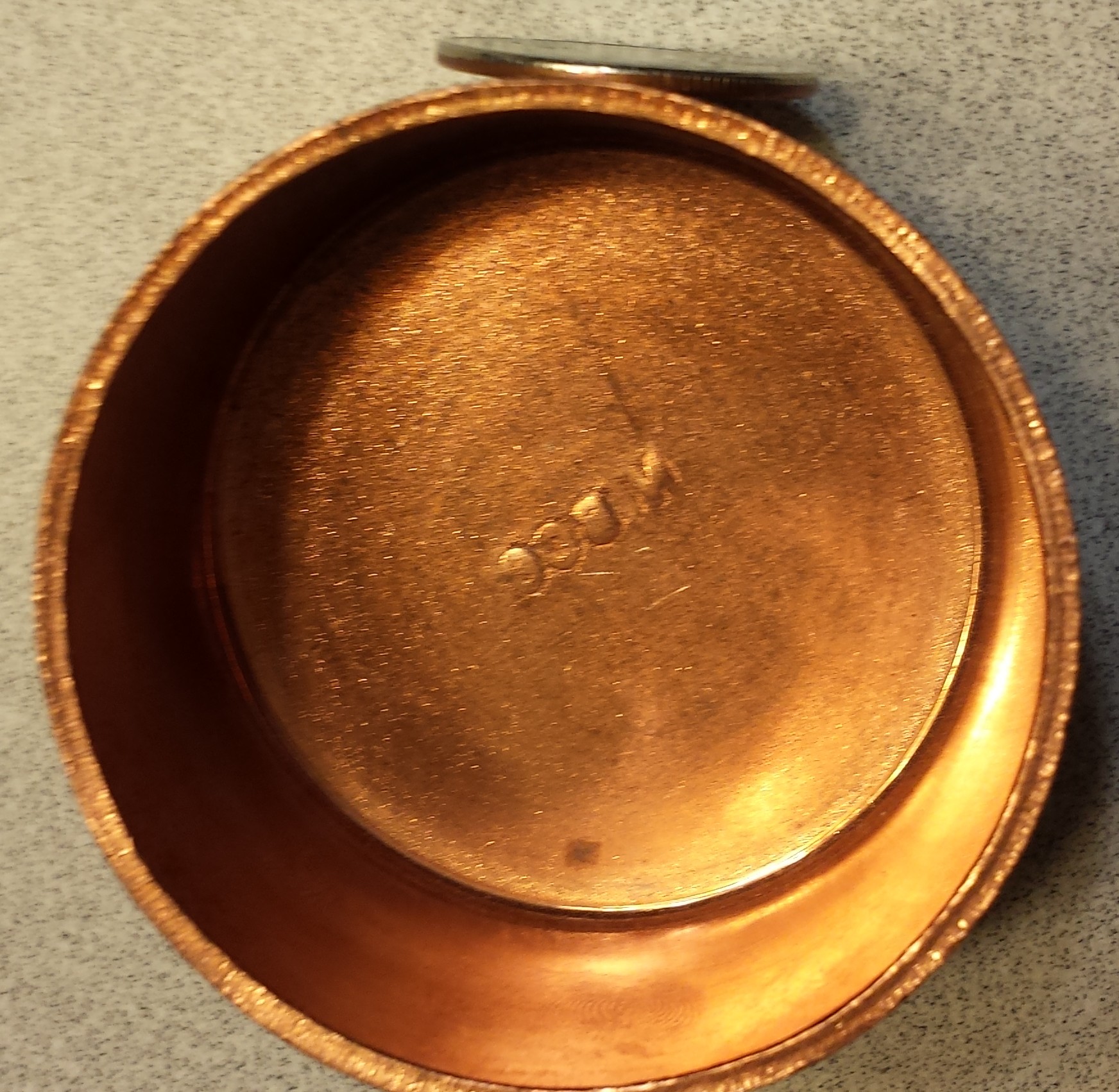
20140128_194050 20140128_194035 20140128_194017 2" copper endcap, next to a quarter for thickness comparison.

One of my thoughts was to thread (NPT) the outside of a 2″ copper endcap, apply teflon tape, and thread it into a 2″ stainless steel endcap.  I would bore a centered hole in both caps, and the copper cap would be threaded onto the heating element, flat side toward the element.  An elbow would be threaded into the stainless steel cap and attached to a piece of stainless steel pipe through which wiring for the element would have been run.

I believe I have a threader which would have allowed me to thread the copper endcap, but I had several concerns about the longevity of the design in addition to the questionable cost-effectiveness.  Even Chinese stainless steel 2″ endcaps are north of $20, and that would not include any boring/threading/machining.  I was also concerned about the durability of the union between the relatively thin copper endcap (shown with a quarter standing beside it in the picture above for comparison) and the threaded fitting of the element.

January 25, 2014

DIY Pin Lock Socket – Mr.Beer® Fans Forum

Filed under: Fabrication,Hacks,Links — Tags: — Landis V @ 3:01 pm

http://www.mrbeerfans.com/ubbthreads/ubbthreads.php/topics/276496/DIY_Pin_Lock_Socket.html

DIY post/pin socket for pin lock kegs.

DIY post/pin socket for pin lock kegs.

I was at Menards the other day and it crossed my mind that I needed make one of these so I could place the o-rings on my pin lock dip tubes.  I picked up a Mastercraft deep well 13/16″ socket, finally got around to cutting the slots in it today, and it works great.  My socket as it came out appears to the left, it took about 15 minutes with some very flimsy/lightweight cutoff wheels in my Dremel-like tool.

As I was looking at the picture, it occurred to me that it might save someone some time in the future if they could simply mark and cut rather than line up and mark the pins.  Pretty straightforward to do with either a six point or twelve point socket.  I’ve attached a couple of pictures below that show which of the points you’d need to cut for both a six and twelve point socket.

12pointsocketpinlock hexpinsocket

DIY Stir Plate Build

Filed under: Fabrication,Food and Drink,Links,Uncategorized — Tags: , — Landis V @ 11:10 am

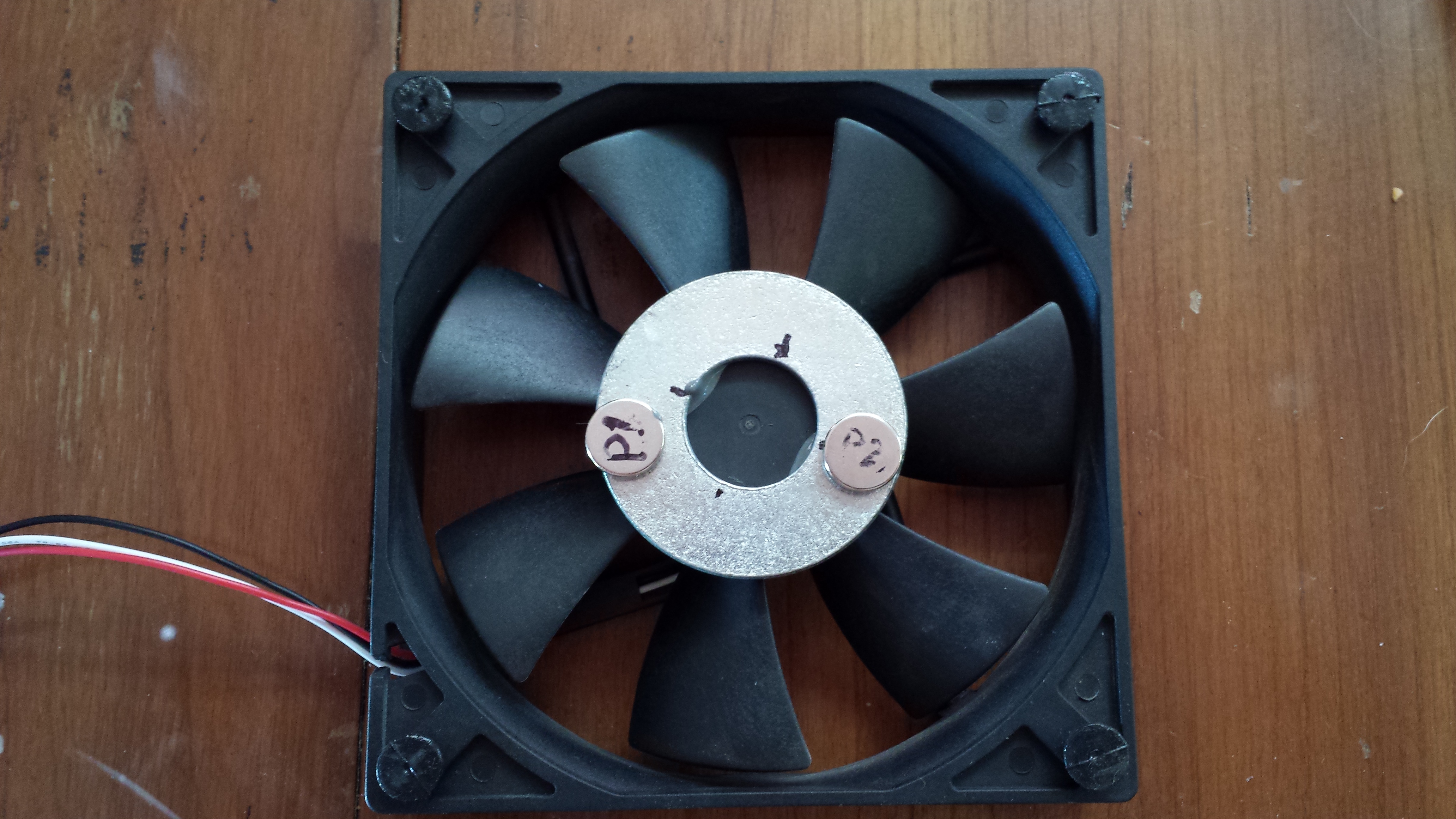
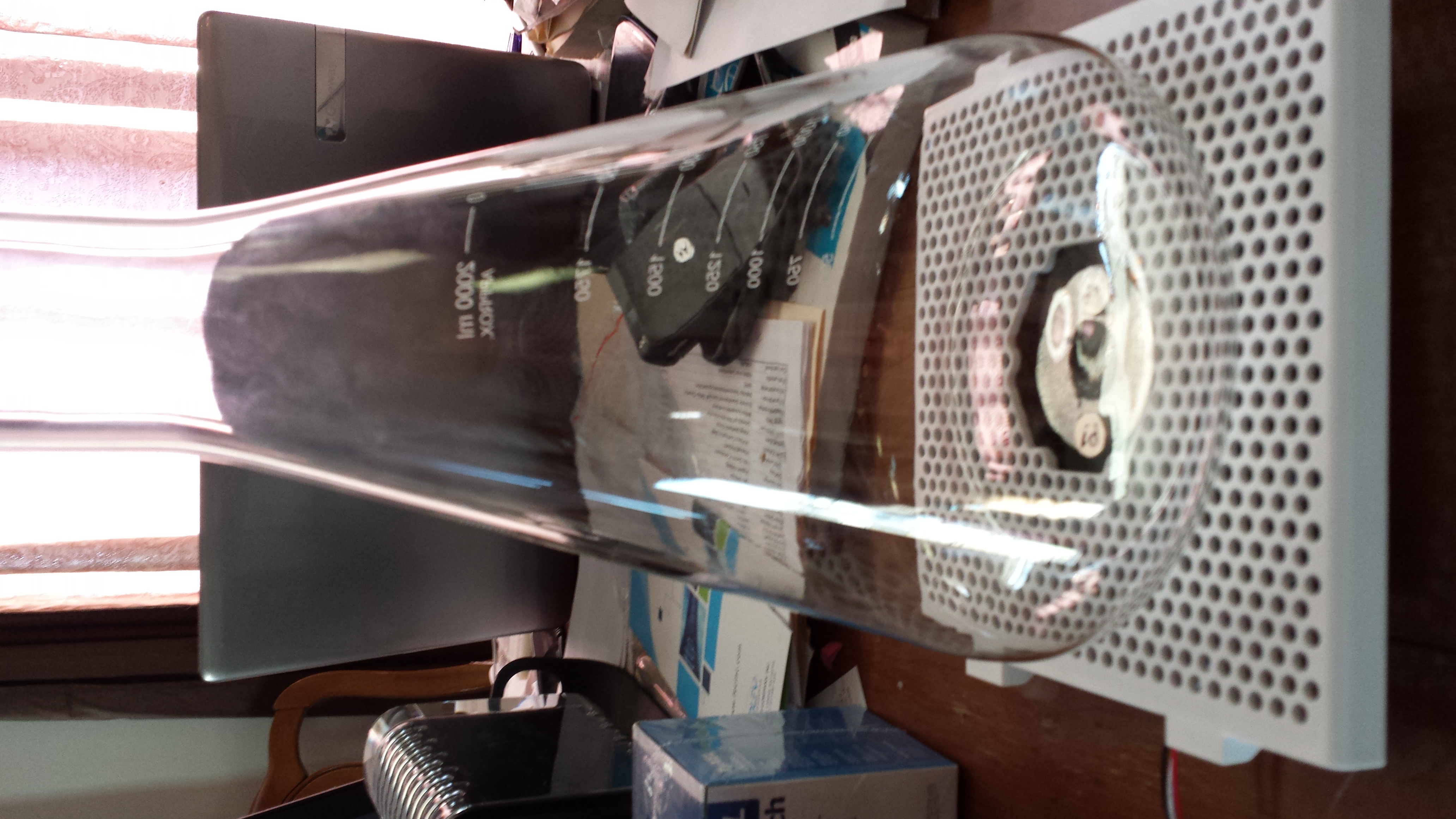
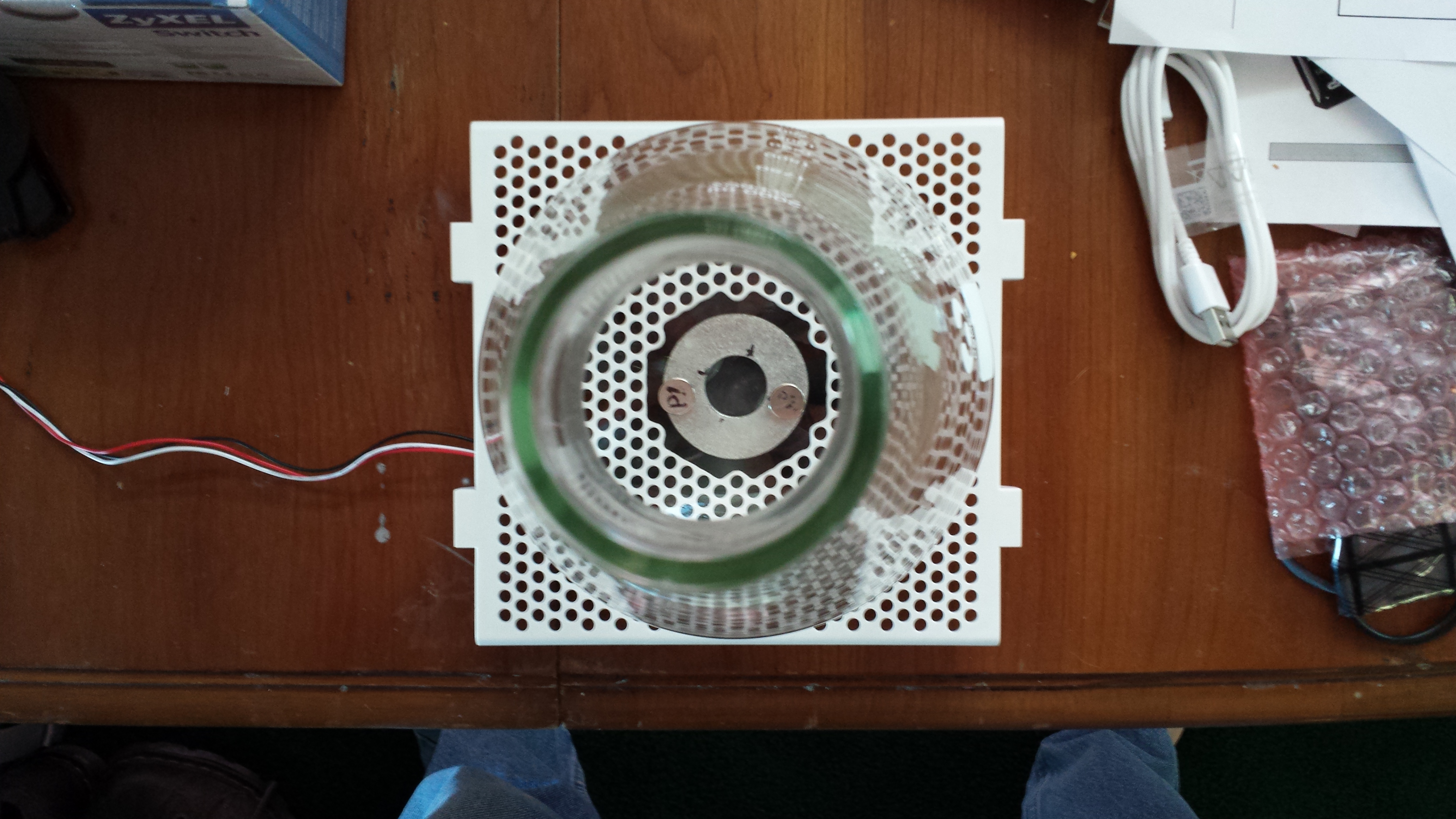
I recently posted a link to a DIY stir plate build and needed to get started on my own list to keep track of supplies I have, supplies I need, and where I’m at in that task.  (Note:  As of 2/5, I completed this mostly with equipment I had on hand.)

Part List

List of parts and prices for the build.

  • 120mm Computer case fan
    • Had on hand, typically available for <$5 if you look (techbargains.com, slickdeals.net)
  • Erlenmeyer 2000ml flask
    • (Purchased) Amazon $14.25 (10-Jan-14)
  • Epoxy
    • JB Weld, had on hand, Menards $4.67/Amazon $6.64/Wal Mart $4.67
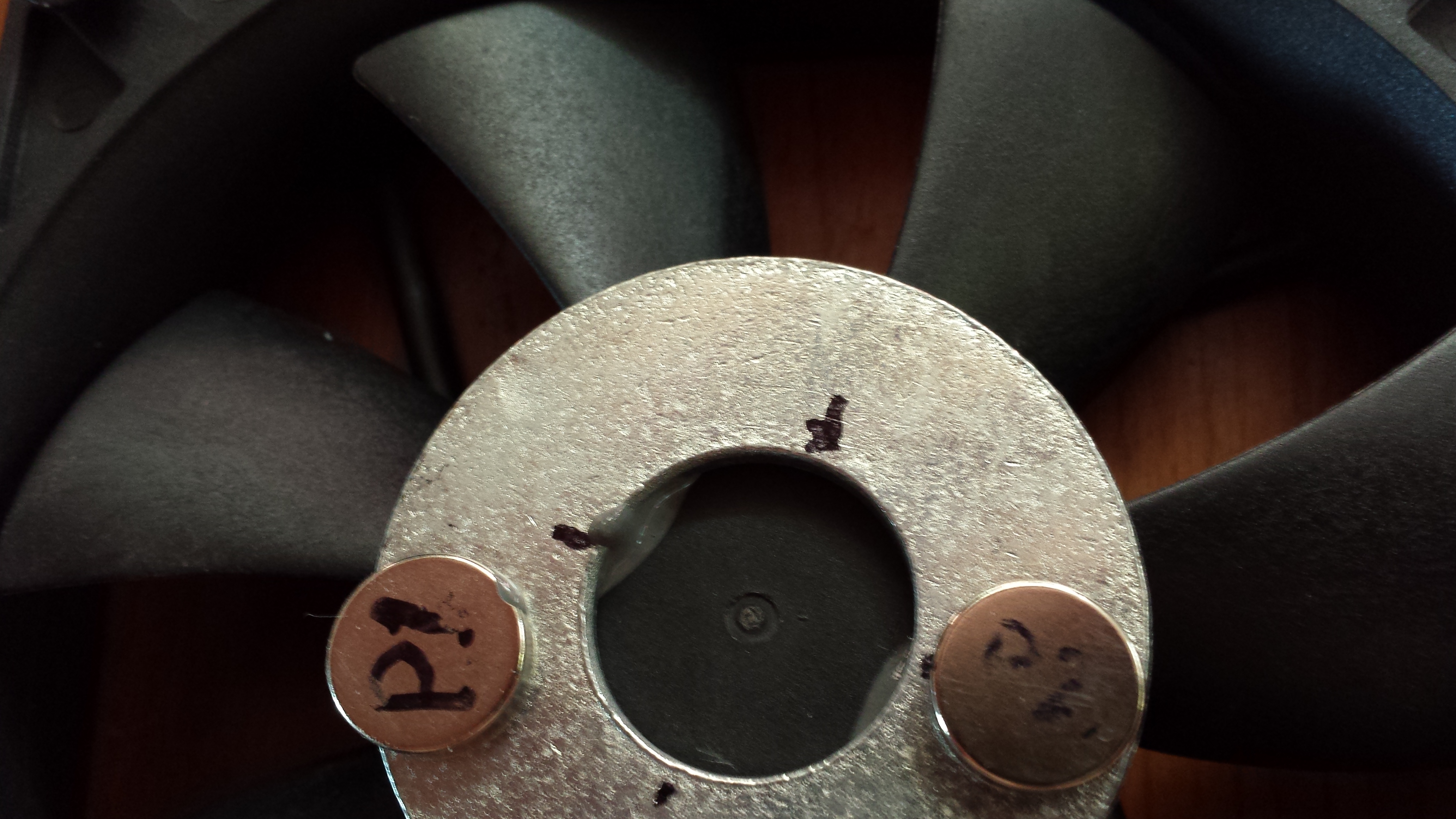
      • I was surprised to discover that this stuff apparently does actually contain steel.  While affixing the washer to my fan, I observed a small finger of the blended epoxy creeping out from under the washer and towards my magnet.  I’d suggest marking the position of your magnet(s) and centering based on your marks, and not attempting to assemble with the magnets in place.  Otherwise, you may find them epoxied in place!
  • Misc hardware (nuts/bolts/washers for table attachment/standoff)
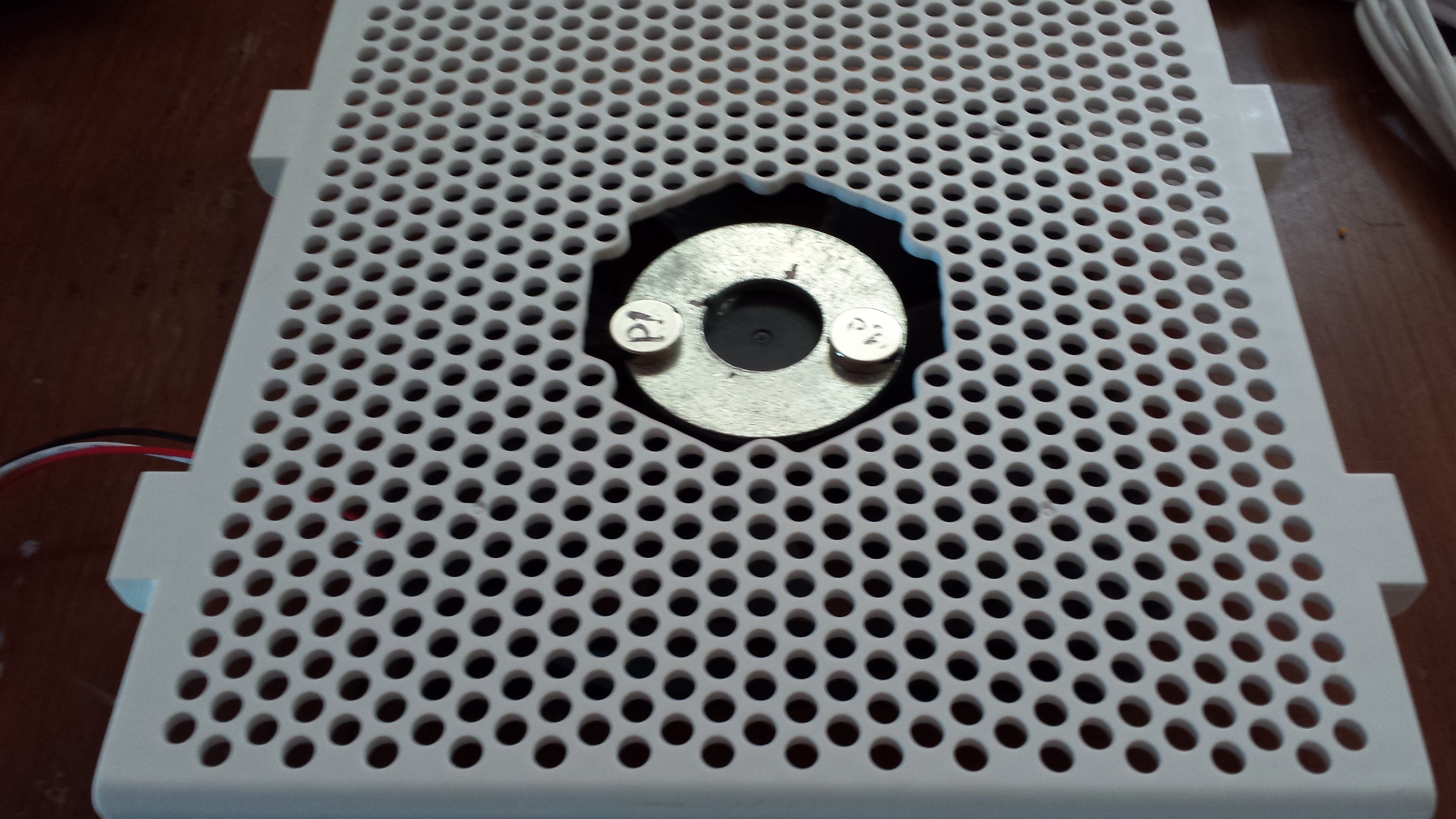
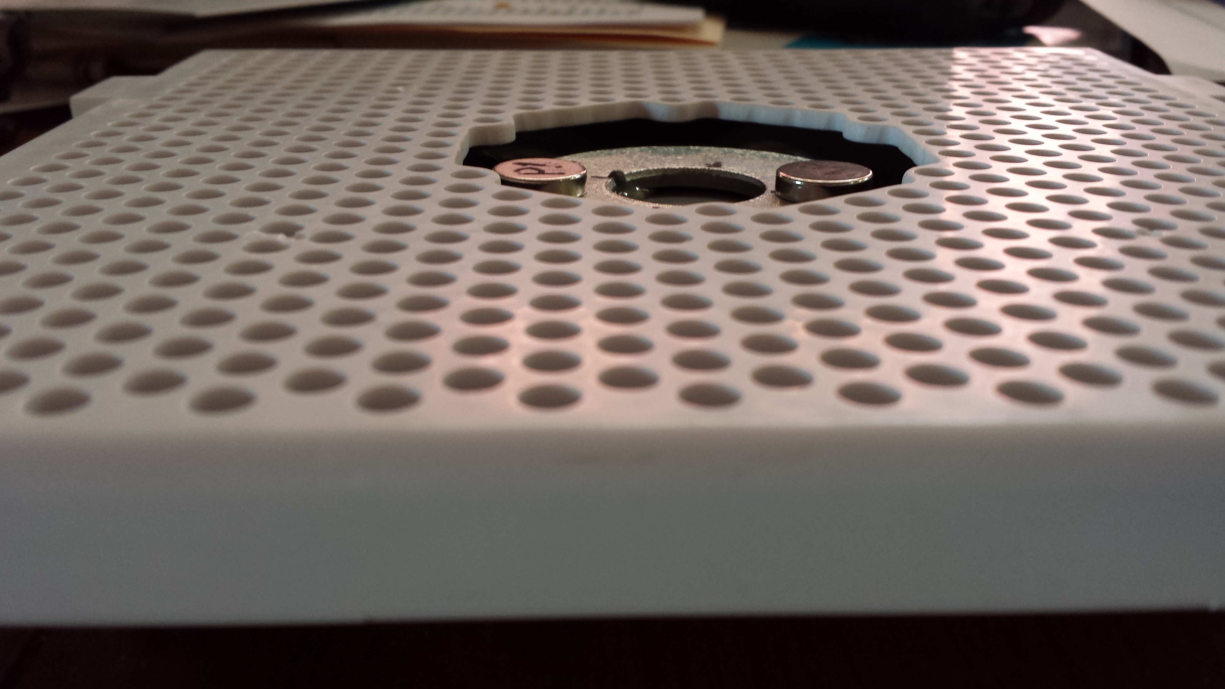
    • Had on hand.  Used rubber anti-vibration pads that came with the case fan I replaced with the one I had on hand.  I just set the table on top of the fan on the side with the rubber pads protruding and approximately center it.
  • Neodymium/rare earth magnets
  • Stir bars
  • Table to support Erlenmeyer flask above fan
    • Had on hand/made from a ~10″ square piece of plastic, probably about 1/8″ thick, that came from one of those old lights that uses the heat from the bulb to turn an impeller (propeller? should look this up I guess) to cast a rotating image on walls/ceiling through a cellophane medium.
  • Washer (large)
    • Had on hand; if you don’t, less than a buck at the local hardware.
  • 12V Power supply
    • I had one of these on hand that already had a power switch, and had the quick wiring disconnects so I could just tie it right onto the red and black leads from my fan.
  • Potentiometer
    • I picked up a potentiometer from Radio Shack to allow me to control the speed, but I’m not sure I’m going to need it.

Build Process

The build process is more or less as described in the original article I linked to.  I simply centered the large washer on the hub for my case fan and glued it in place with J-B Weld epoxy.  As I noted, J-B Weld does appear to actually contain some steel, so I recommend mounting the washer without having the magnets stuck to it.  Once the epoxy hardens, gently place the magnets on the washer approximately across from each other, spin the fan, and try to balance it as well as possible.  I found that you can place the stir bar across the magnets directly and it helps to visualize how well it will be centered above the fan hub, and ultimately how efficiently and quietly the stir plate will operate.

Below are a few build/post build pictures.

20140125_150610 20140125_150618 20140125_150701 20140125_150725 20140125_150910 20140125_150943

Video of initial test

January 24, 2014

Bev-Seal Ultra 235 Notes

Filed under: Fabrication,Food and Drink — Tags: , — Landis V @ 10:22 am

Reason and Purpose

When I first started to consider the process of fabricating my own keezer, there was a great deal I didn’t know and many components with which I was unfamiliar.  I did know that vinyl tubing has a tendency to influence the mediums it transports, and I wanted to get an idea how much influence “beer line” typically has upon its subject.  It was this threadHBT60380 which first introduced me to Accuflex’s Bev-Seal Ultra Series 235, and from there I was off to the races.  I’ve reached the point where the amount of information I’ve accumulated on this product is worthy of its own post, which will hopefully allow me to take a little bit of noise out of some of my other marginally related posts, instead substituting a link back here.

Description and Characteristics

Bev-Seal Ultra Series 235 tubing hoseThomasnet is a flexible barrier tubing manufactured by Accuflex.  They describe it as a truly flushable dual barrier product allowing quick flavor changes, even for pungent flavors.  It utilizes their trademarked Glas-Flex polymer inner barrier liner, which they claim is “flushable, glass-smooth, non-porous, non-absorbent, non-reactive, taste-free, FDA sanctioned, and NSF51/NSF61 accepted.”Accuflex Kal on the Homebrew Talk forums vouches for these characteristics with independent testing of water left sitting in distribution lines. HBT60380 At the time that thread began, this product was unavailable in 3/16″ ID – which tends to be highly suitable for the short runs commonly found in home built distribution systems – and apparently remained that way for several years.

Forum thread discussing/recommending use of 3/16″ Bev-Seal to reduce foaming, especially on shorter runs and recommendations on how to install.

For 3/16″ ID tubing, 2PSI restriction per foot (necessary for balancing the distribution system), and volume of .18oz per foot (nice to know so I can tell how many ounces of flat beer I might get in a pour after a long rest)  per CHI 24-Jan-14.  At least one source indicates this is far higher than the restriction rate they have found, reporting restriction of .45PSI.

Part number for 3/16″ID series is 235-05620-XX, where XX represents line numbering and/or color on the tubing.

A typical Part Number is 235-08620-XX for a 500 ft. spool of 3/8” size tubing, where “XX” indicates the number to be imprinted (use “00” for unnumbered tubing). The color coding is in the form of  colored strips 120° apart, and number and color coding is as follows: XX = 01 – Blue; 02 – Black; 03 – Red; 04 – Green; 05 – Yellow; 06 – Orange; 07 – Brown; 08 – White; 09 – Pink; 10 – Purple; 11 – Blue; 12 – Black; 13 – Red; 14 – Green; etc. Thomasnet

Footnotes

Accuflex:  Accuflex Bev-Seal Ultra product catalog, retrieved 24-Jan-14, LV
HBT60380: Homebrew Talk forum post documenting testing of a variety of tubing types and their impact on flavor, retrieved 24-Jan-14, LV
Thomasnet: Thomasnet spec sheet for Accuflex products, retrieved 24-Jan-14, LV

January 9, 2014

How to make Belgian Candi Sugar | An Engineer and His Carboy

Filed under: Food and Drink,Knowledge and Learning,Links — Tags: — Landis V @ 10:26 pm

http://joshthebrewmaster.wordpress.com/2010/11/27/how-to-make-belgian-candi-sugar/

I heard about making one’s own candi sugar from a friend today, so this made my list as well.  I’m pleasantly surprised at how straightforward it is, and another item on the seemingly endless list of things one can learn without half trying once introduced to the hobby of brewing.

January 4, 2014

Kegerator/keezer notes for future analysis

Filed under: Fabrication,Food and Drink,Hobby Engineering,Links,Projects — Tags: — Landis V @ 11:58 pm

Note:  This document is a work in progress and will change frequently.  It’s my kegerator scratch pad if you like.

I got at least a portion of the components for my keezer setup this afternoon, along with a 40 gallon boil kettle and several carboys.  Now we can really make beer, as well as some mead and perhaps some wine in the near future as well.  Making a few notes on the buildout for the keezer.  I don’t plan to complete a final build just yet as I’m only doing four pin lock kegs at present, but I don’t want to have to replace core components such as tubing when I upgrade.  I figure it’s best to just start with fresh o-rings and gaskets in the kegs from the outset.

Article that led me to Bev-Seal Ultra 235.
Forum thread discussing/recommending use of 3/16″ Bev-Seal to reduce foaming, especially on shorter runs and recommendations on how to install.

Dip tube insert that allows reduction of serving pressure or line length
http://www.mcmaster.com/#74695a58/=qe6iu6, discovered from thread at http://www.homebrewtalk.com/f35/cure-your-short-hose-troubles-100151/index2.html. Isopropyl alcohol and/or boiling only to clean due to delryn decomposition (highlighted in several posts in the thread).

BYO article on balancing your distribution system.  And another post from a fluid mechanics expert that points the way if I decide to get into the technical details and calculations for accurate determination of hose lengths, though I’m not sure how readily the information about the Bev-Seal Ultra resistance characteristics will be, and as someone else had mentioned it’s also possible that variance/inaccuracy in our regulators could cause a lot of the variations people seem to experience with line lengths.

Adventures in Homebrewing
Complete 4-keg pinlock system (excluding kegs and tank) for $382.99; can add 10# tank for $60. Part/item 4470-7, $382.99

O-rings, 5 sets, post and dip tube, $4.50 shipped – http://www.ebay.com/itm/5-Homebrew-Beer-BALL-or-PIN-LOCK-Cornelius-Keg-Post-Dip-Tube-RED-O-ring-Kits-/151173485689?pt=LH_DefaultDomain_0&hash=item2332a45479

Good deal on set of ten gasket/o-ring kits for ball/pin lock on eBay, added to watch list; somewhat up in the air as I understand pin lock o-rings to be slightly thicker than ball lock.

Freezer Layout and Dimensions for Kegerator/Keezer

Measurements

  • Front to back (outside, corners):  21 11/16″
  • Front to back (outside, middle):  21 5/8″
  • End to end (outside, corners):  41 1/4″
  • End to end (outside, middle):  41 3/16
  • Front to back (inside, inner lip):  16 1/4″
  • End to end (inside, inner lip):  35 13/16″
  • Front to back (inside, outer/upper lip):  17 9/16″
  • End to end (inside, outer/upper lip):  37 1/8″
  • Lip width (inner):  7/16″
  • Lip width (outer/upper):  2″
  • Hump width:  11 1/8″
  • Non-hump width:  24 7/8″
  • Hump depth (top of hump to top of inner lip):  18 11/16″
  • Non-hump depth (bottom of main compartment to top of inner lip):  28 3/4″
  • Body front to back (outside):  21 7/16″
  • Body width end to end (outside):  41″
  • Lid front to back (outside):  21 1/2″
  • Lid width end to end (outside):  41 1/16″
  • Lid height:  1 1/2″
  • Top of lid to top of outer lip:  2″

Open Space Measurements

Measurements of remaining open space with a fill equivalent to six pinlock kegs.

  • Main compartment with 4 kegs, open corner at end (smallest measurement):  5″
  • Main compartment with 4 kegs, open corner next to hump (smallest measurement):  5 1/2″
  • Hump open space at corner with six kegs (approximated), maximum:  6 1/4″ x 7 1/4″
  • Top of keg in main compartment to top of inner collar/lip:  6 1/2″
  • Top of keg on hump to top of outer lip (i.e., minimum collar):  3″

Build Process

Temperature Controller

31-Jan-14

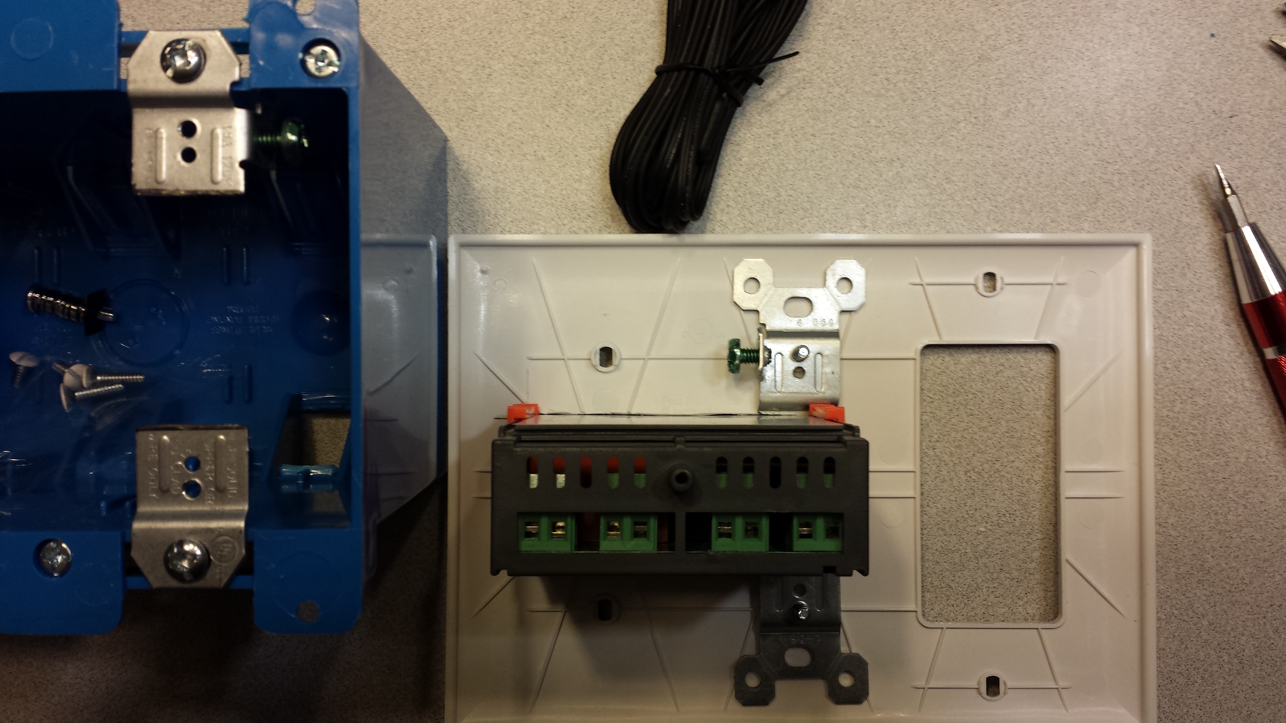
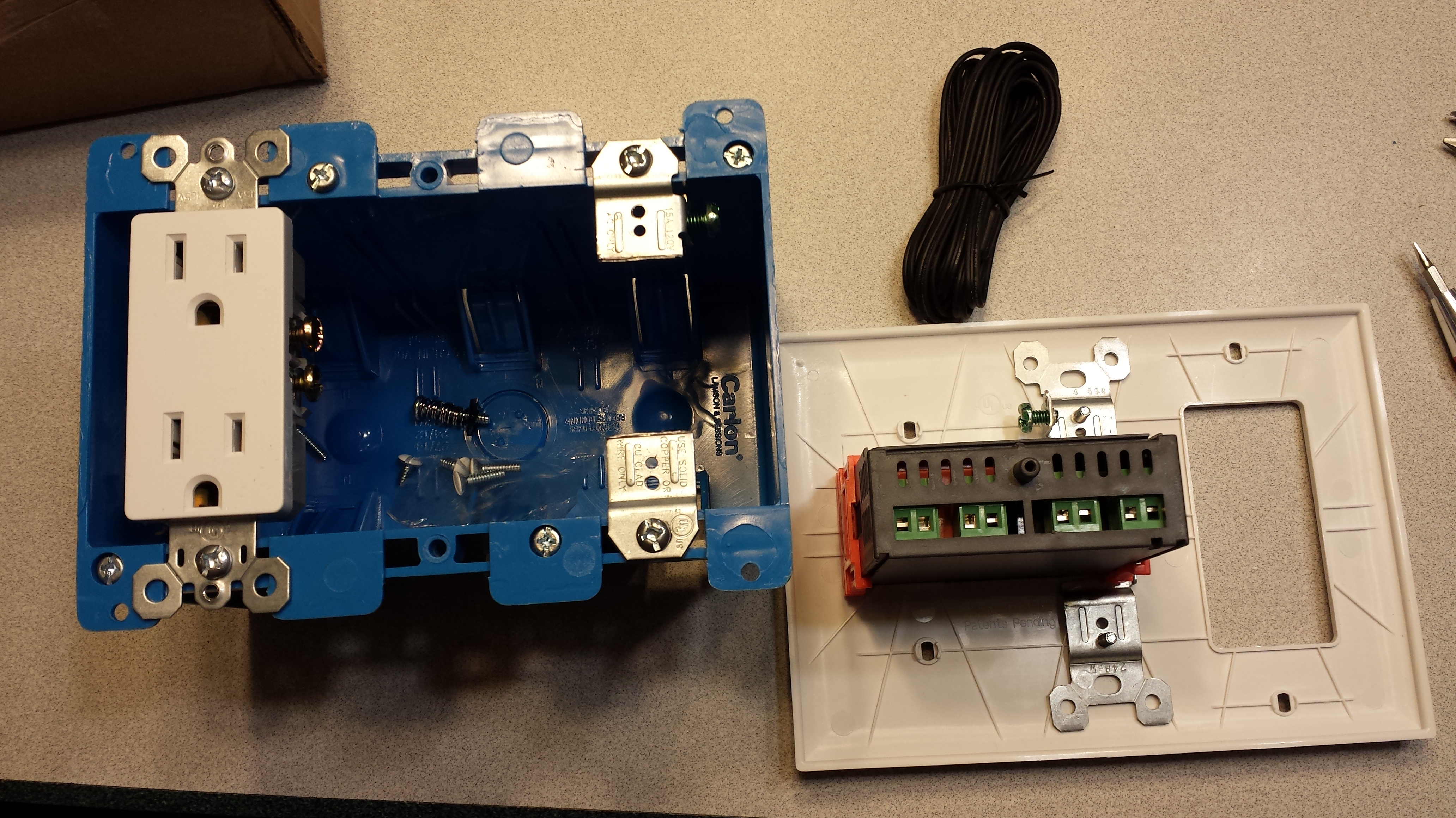
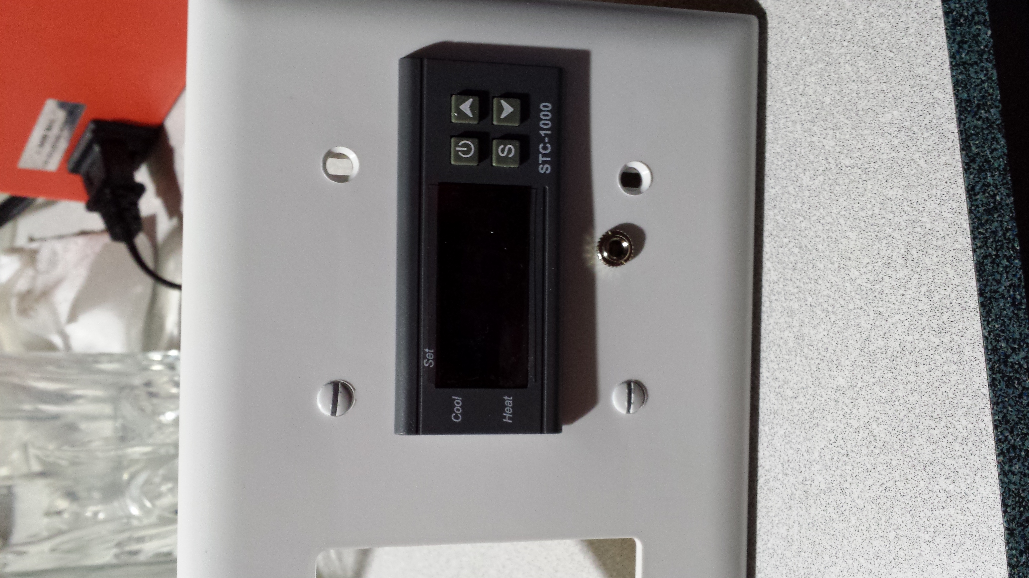
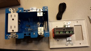
After a false start getting an old work junction box that was only two gang, and both too narrow and too deep for the way I wanted to set up my temperature control unit, I was able to get it mostly put together on Friday (31-Jan-14).  I still didn’t get exactly what I wanted, but I was able to make it work.  Ideally I wanted a faceplate with a rectangular outlet opening on one end and the other two spaces blank.  Unfortunately they didn’t have such a thing at the local big box store, so I got a three gang cover with a rectangle on one end and two regular switch outlets in the other spaces.  I chose this option so I wouldn’t leave any random holes or partial cutouts on the faceplate when I made the hole to mount the controller; its mounting hole will consume both of the switch cutouts completely.
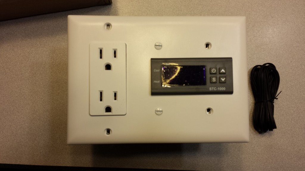
20140131_193850

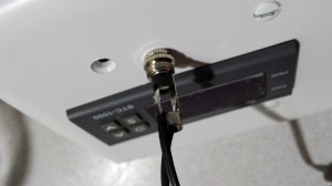
The keezer temperature controller in a “test fit” configuration. I still need to add a connector for the actual temperature sensor, and I think I’ll get a 1/8″ phono jack and plug to accommodate this.

You may or may not have noticed that the mounting holes for electrical cover plates vary with the component installed behind them.  The mount points in the junction box/gang itself are consistent, as all devices mount into them; this is why I wanted the layout I did, so that the space where I make the cutout for the temperature controller itself will mount directly to the box and the outlet space will attach to the outlet.  They don’t appear to make (or the store didn’t have) a mounting assembly that I could use to adapt the gang box mounting holes to fit the narrower spacing of the light switch holes, so I bought a pair of the cheapest generic light switches they had ($.54 each) and removed the actual switch part, then slightly modified them to make two different types of attachment points (see picture below).
20140131_193907 20140131_193919

6-Feb-14

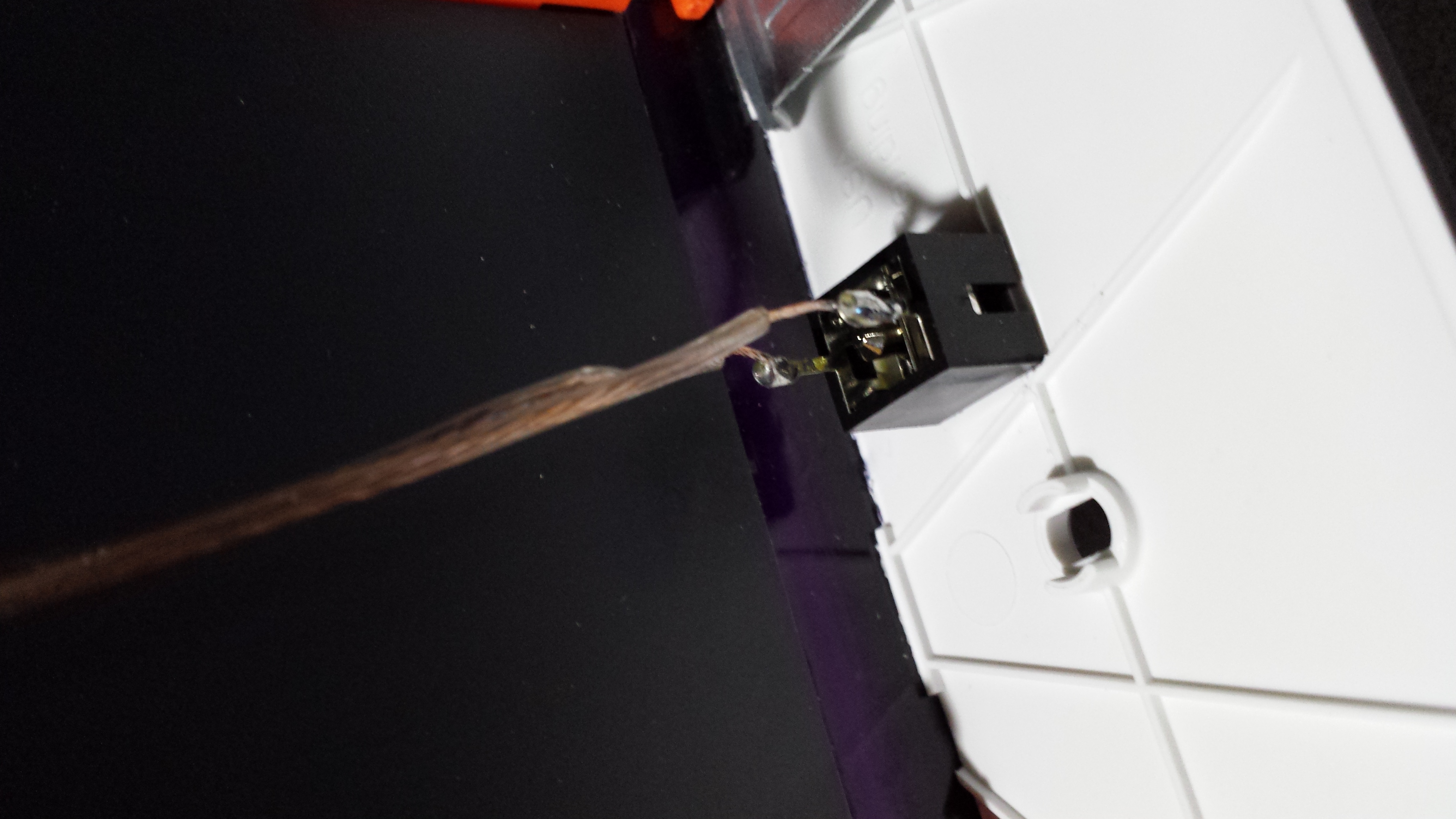
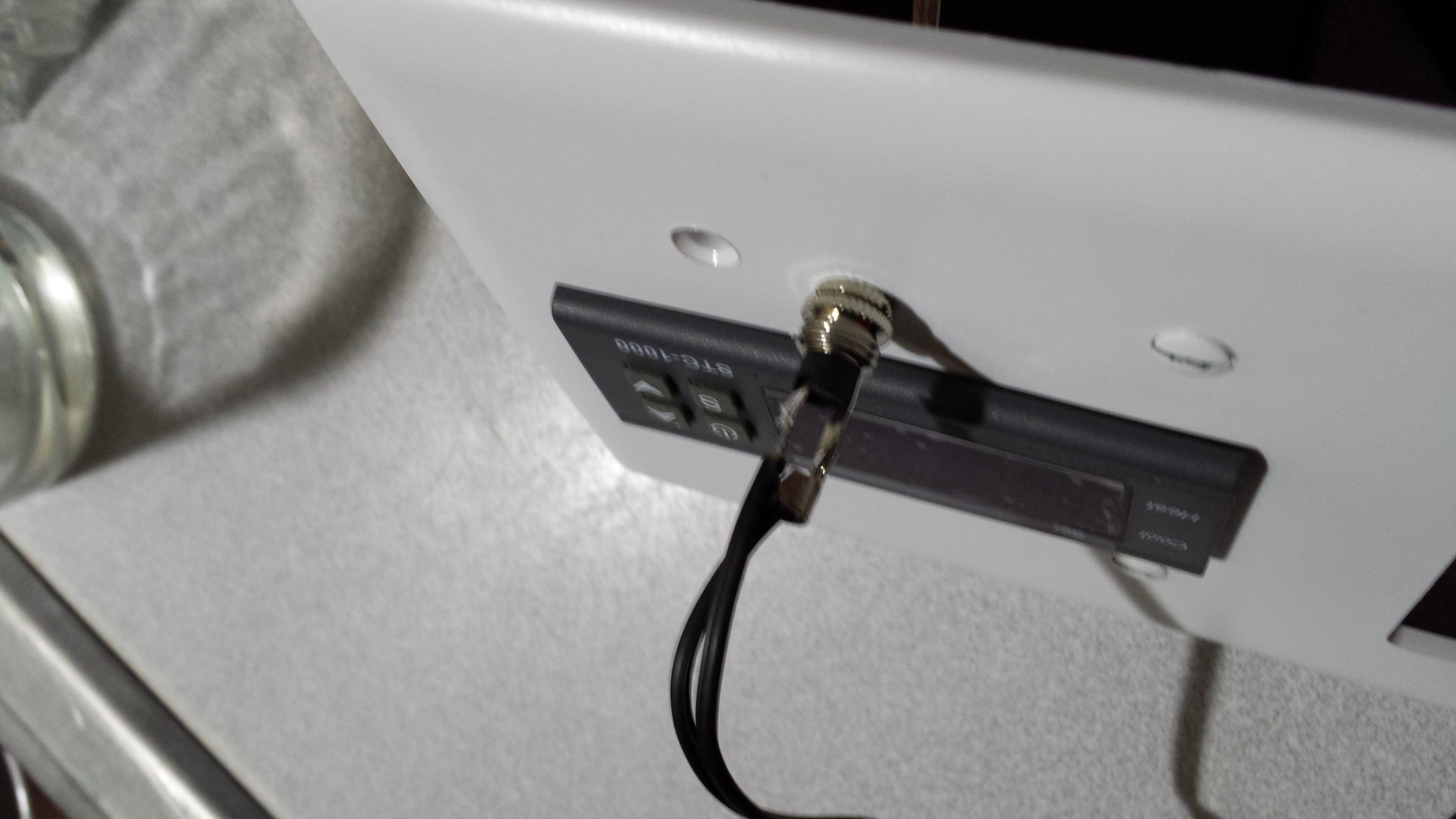
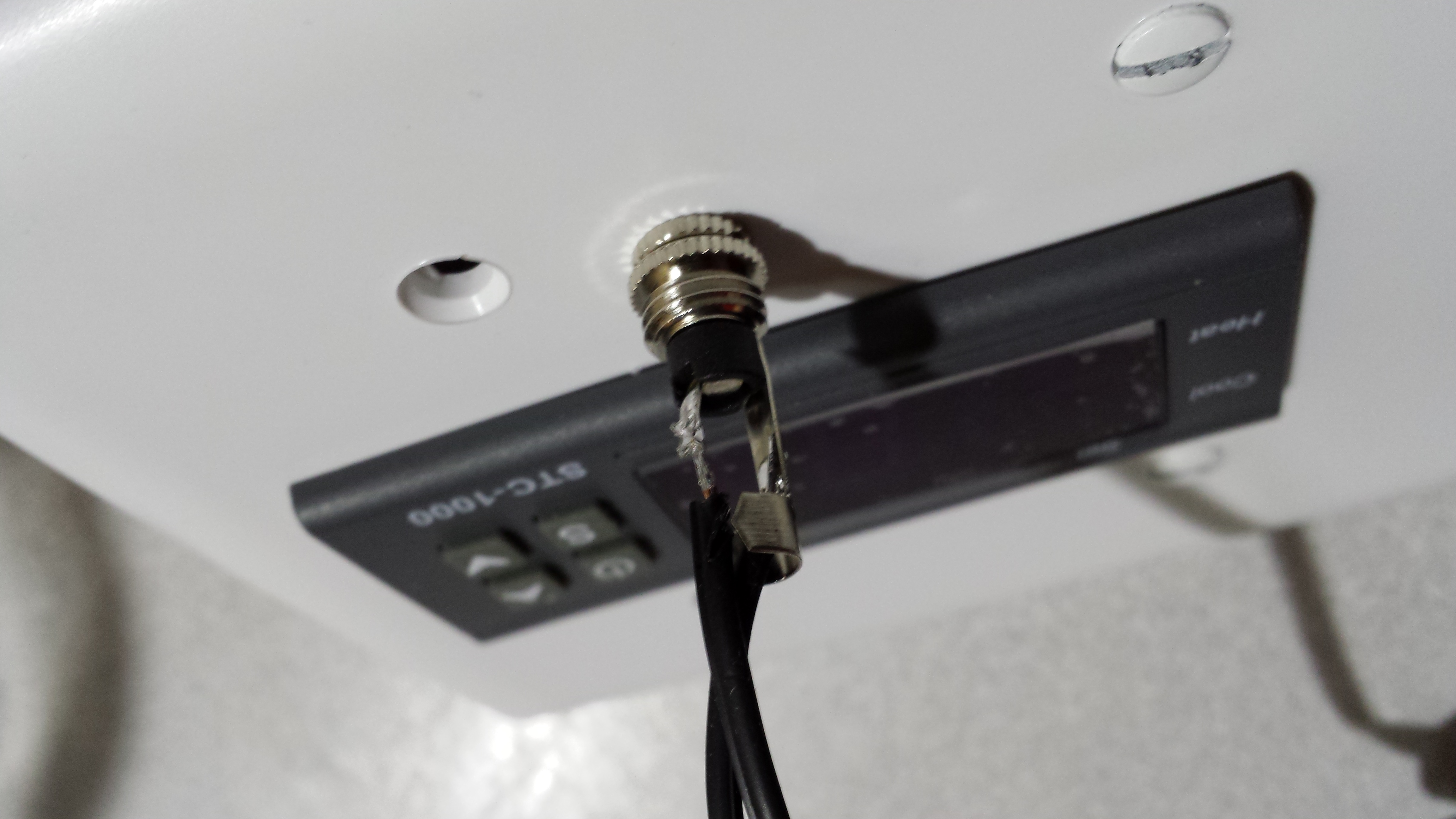
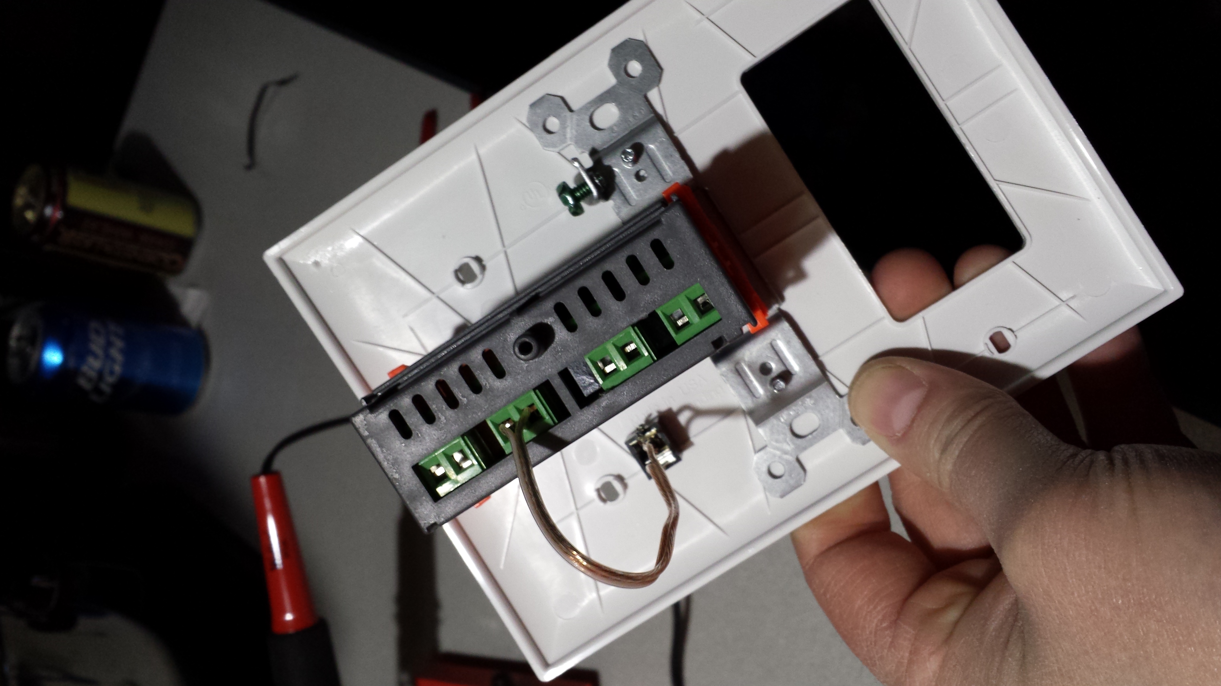
After picking up a few additional parts from Radio Shack to make the temperature sensor modular/disconnectable, I did some wiring this evening.  I can hear the controller relays kicking, but unfortunately it doesn’t appear to be firing the heating or cooling outlets, so I have some troubleshooting to do.
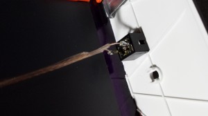
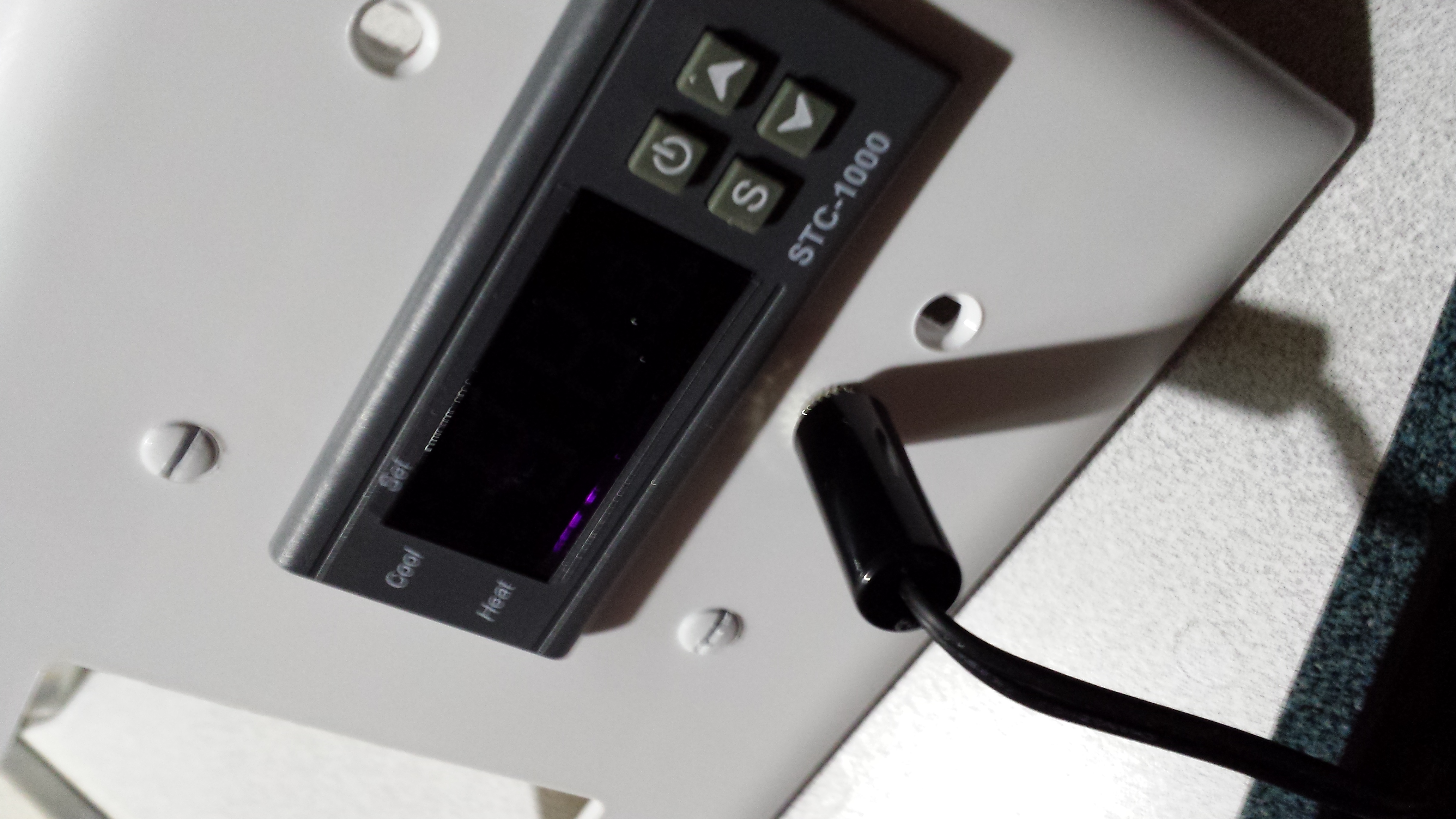
1/8" stereo jack to allow quick disconnect for temperature sensor.  I could have used a mono to match the plug, but Radio Shack didn't have one.

1/8″ stereo jack to allow quick disconnect for temperature sensor. I could have used a mono to match the plug, but Radio Shack didn’t have one.
Soldering the 1/8" male mono plug.

Soldering the 1/8″ male mono plug.

The solder job was better before I had to remove and redo it because I forgot to put the housing on the wires first.
The solder job was better before I had to remove and redo it because I forgot to put the housing on the wires first.

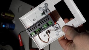
Temperature sensor disconnect in place and wired to the relay.
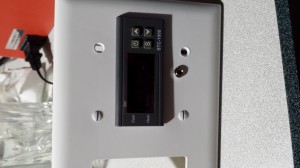
Temperature sensor disconnect in place and wired to the relay.

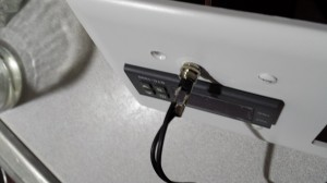
Front view of the finished temperature sensor disconnect.
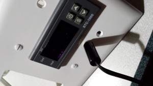
Front view of the finished temperature sensor disconnect.

Temperature sensor disconnect with sensor attached.
Temperature sensor disconnect with sensor attached.

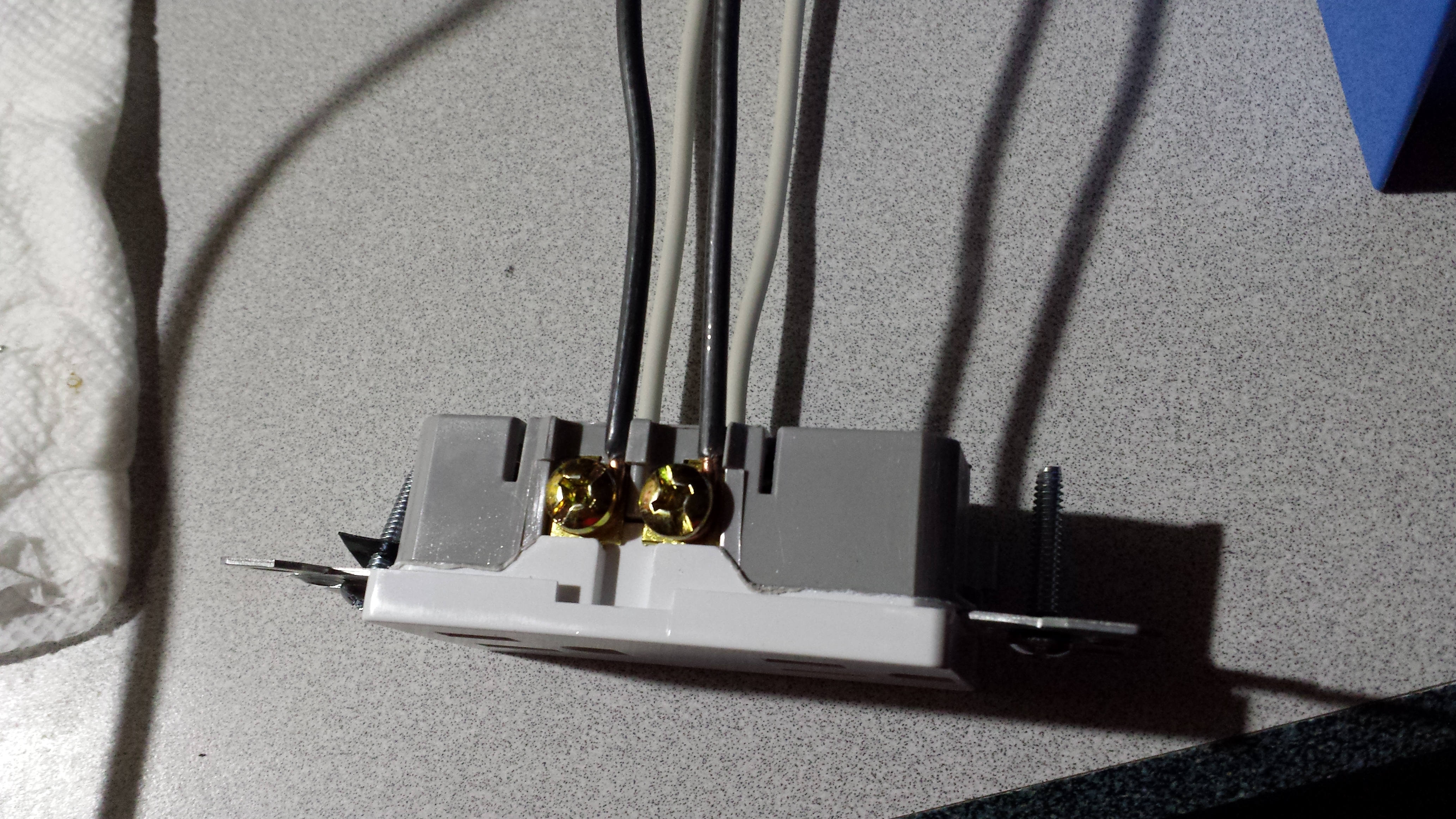
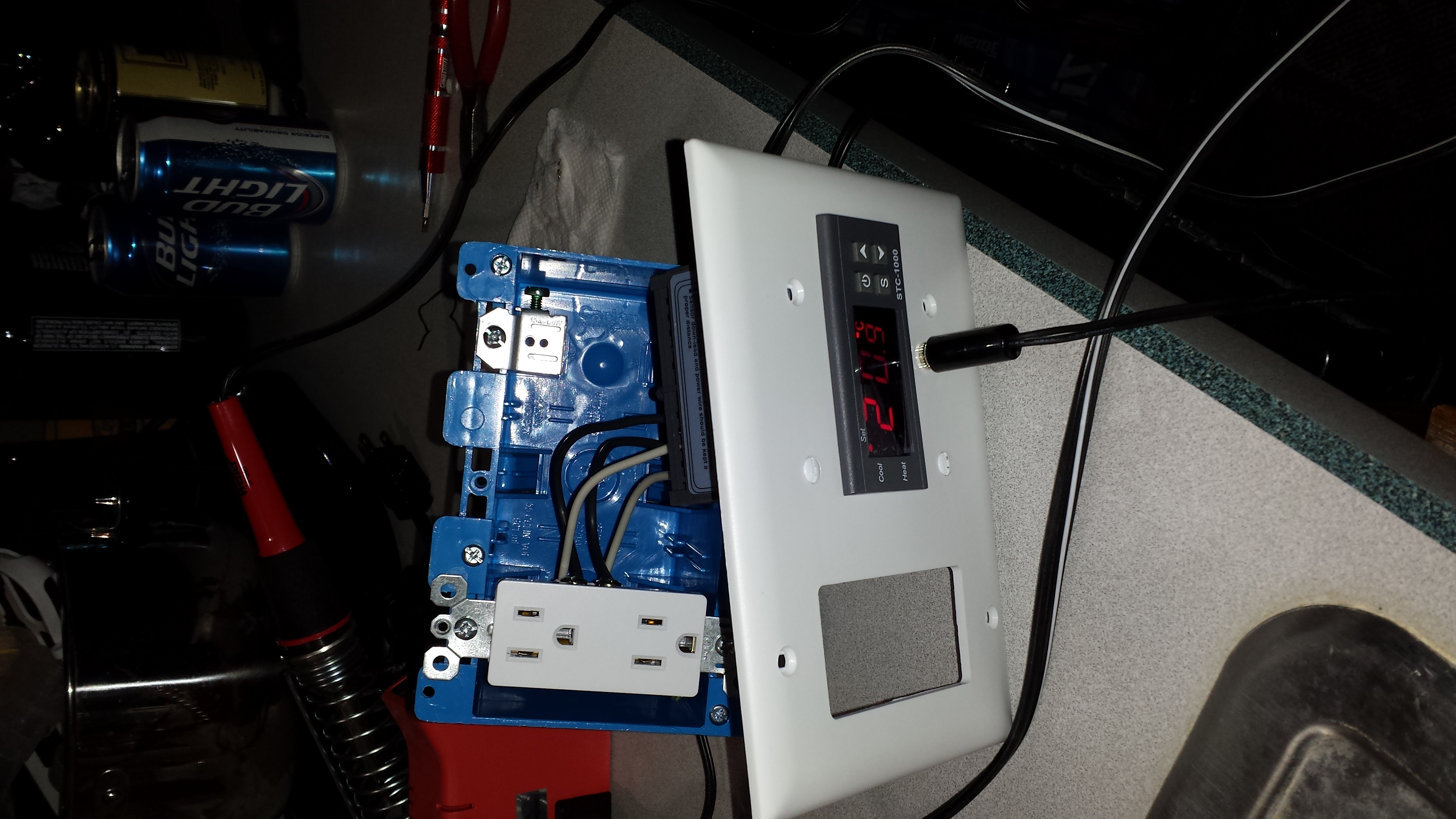
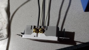
Wiring the outlet.  Note the split outlets (the removable bridge between the screws is... removed).

Wiring the outlet. Note the split outlets (the removable bridge between the screws is… removed).

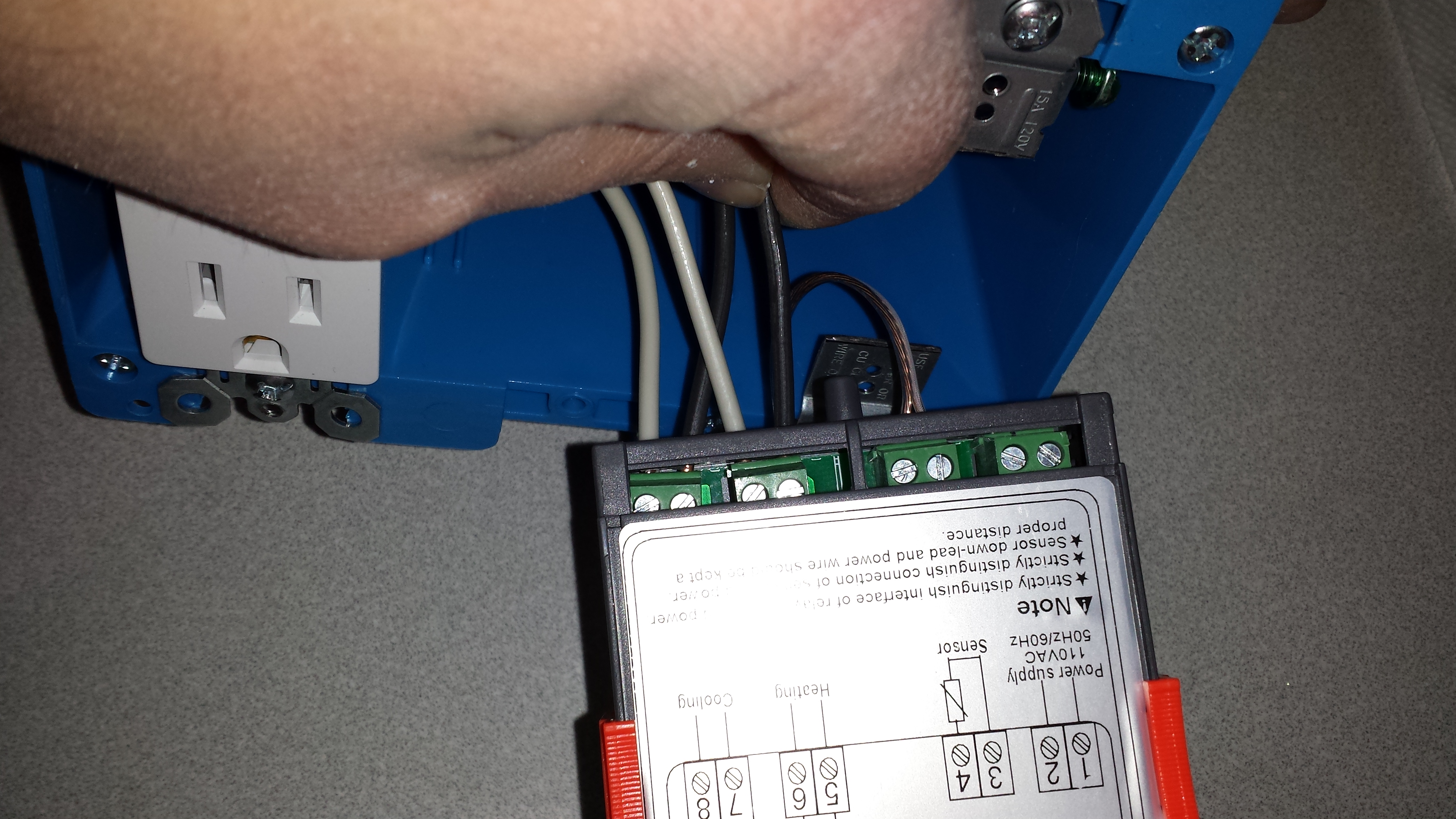
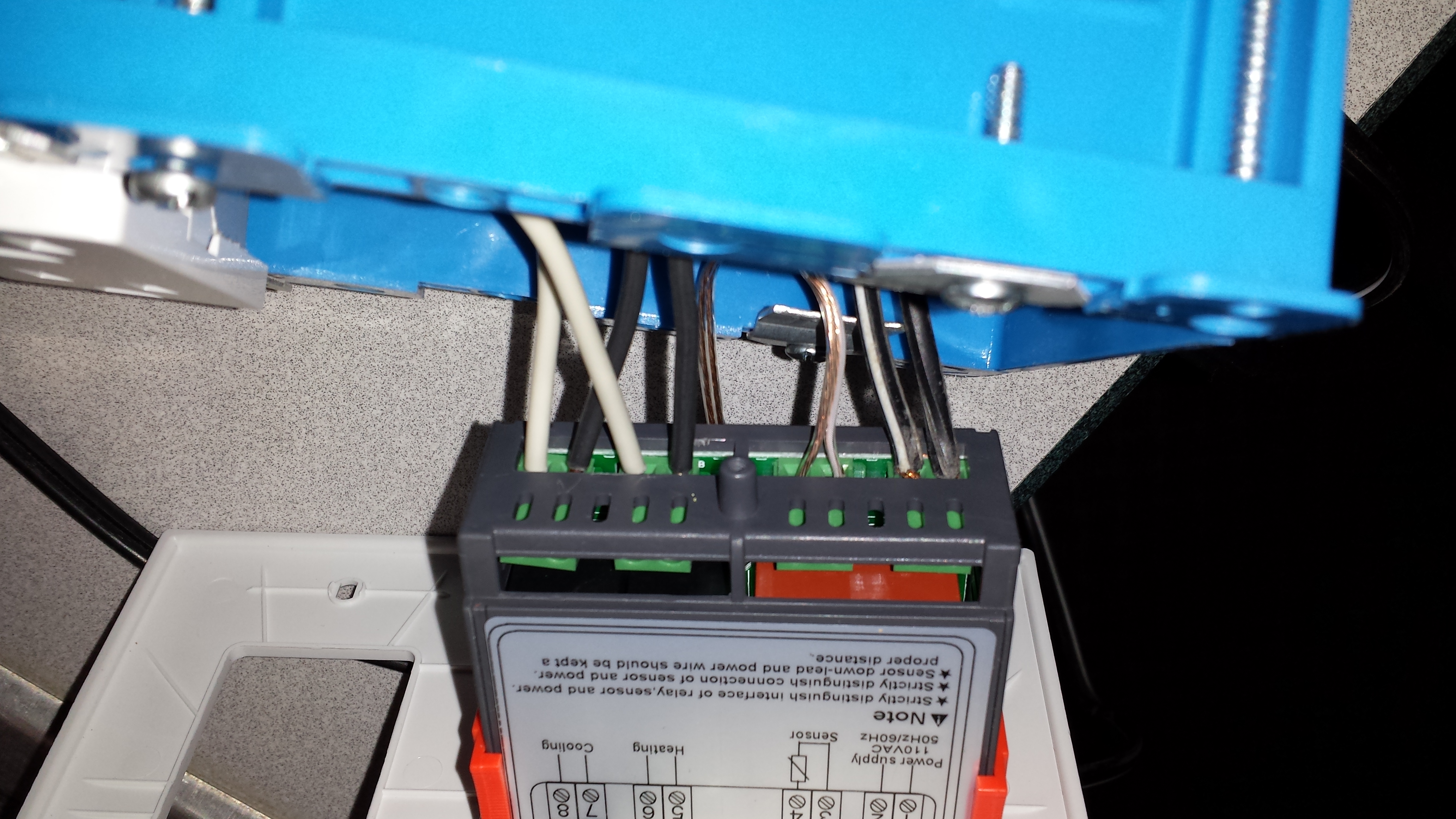
Wiring the outlets into the STC-1000.
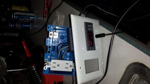
Wiring the outlets into the STC-1000.

Hacked together for a test run with a pigtail I keep on hand.

Hacked together for a test run with a pigtail I keep on hand.

Final view of the connections.  Unfortunately not working, but I think it's an issue with the controler.

Final view of the connections. Unfortunately not working, but I think it’s an issue with the controler.
« Newer Posts — Older Posts »

Powered by WordPress